


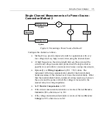

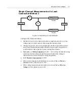
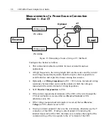
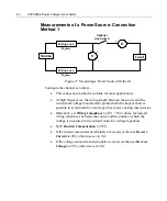
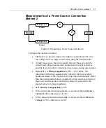
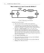


30
2801/2802 Power Analyzer User Guide
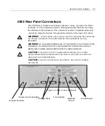
for all interface signals within the interface connectors except for the Ethernet
connections (which are transformer isolated according to the applicable
Ethernet standards). This area is electrically connected to the negative side of
the DC power input via an RF pi filter network having a low DC resistance.
Notes on Grounding:
Between the two ground areas there is a 50ohm (1%) power resistor in
parallel with a 1000pF/50V ceramic capacitor for RF filtering.
The T input connections are isolated from the Internal Electronic Ground
via a nominally 50ohm (1%) power resistor. An isolating current
transducer having sufficient safety rating for the signals being measured
MUST be used when using this input.
The A and Line Switch connections are fully isolated from the Internal
Electronic Ground using transformer isolation to the requirements of
EN61010. This isolation is 100% tested to 4.5kV peak.
The V connections are fully isolated from the Internal Electronic Ground
using transformer isolation to the requirements of IEC61010. This
isolation is 100% tested to 4.5kV peak.
The V connections are resistively isolated from each other with nominally
1Mohm to the requirements of EN61010 in no fault, single fault and
dual fault conditions. This isolation is 100% tested to 2kV peak.
Mechanical isolation is provided between the V connections and the A and
Line Switch connections, which is well in excess of the class ratings of
either set of terminals, there are no electrical signals between these
connections.
Because of the use of transformer isolation, there is very little current
flowing between the UUT terminals and the ground of the product. The
isolation impedance is >10
9
ohms and the capacitance is typically a few
10s of pF.
The EN61010 ratings in each application category for each terminal are
stated on the rear panel of the product next to the terminals.
Содержание Xitron 2801
Страница 1: ...USER GUIDE 2801 2802 Advanced Single and Dual Channel Power Analyzers...
Страница 2: ...2 2801 2802 Power Analyzer User Guide...
Страница 10: ...10 2801 2802 Power Analyzer User Guide...
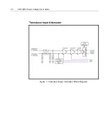
Страница 19: ...Functional Description 19 Voltage Input Attenuator Figure 2 Voltage Input Attenuator Block Diagram...
Страница 101: ...Printing Results 101 Figure 66 Configuration Printout...
Страница 102: ...102 2801 2802 Power Analyzer User Guide Figure 67 Waveform Channel 1 Real time...
Страница 103: ...Printing Results 103 Figure 68 Waveform Channe1 Distortion...
Страница 104: ...104 2801 2802 Power Analyzer User Guide Figure 69 History Chart VOLTS ACDC Trends View...
Страница 105: ...Printing Results 105 Figure 70 History Chart AMPS PERCENT THD Extents View...
Страница 106: ...106 2801 2802 Power Analyzer User Guide Figure 71 Harmonics Listing page 1...
Страница 107: ...Printing Results 107 Figure 72 Harmonics Listing page 2...
Страница 145: ...Sending Commands and Interrogatives 145...
Страница 147: ...Appendix A Physical Specifications 147...
Страница 153: ...Appendix B Measurement Specifications 153...


