Using the Power Analyzer
65
LINE SWITCH & INRUSH DETECTION
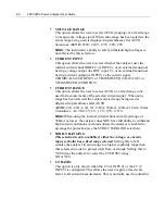
This option allows the user to define what type of signal is being controlled
by the internal line switch:
o
NONE
If this is selected, the internal line switch is continuously held in
the ON state.
o
INTERNAL
If this is selected, the internal line switch will turn on (when
commanded to do so) at the user-entered line switch phase of the
applied voltage signal and will turn off (when commanded to do
so) at the zero crossing of the current signal.
o
EXTERNAL
If this is selected, an external line switch can be used to switch
signals without regard to phase or current state. The Digital I/O
can be used to control the external line switch (See SETUP
SYSTEM)
Note:
Selecting DC when using an AC signal at large currents
may degrade the reliability of the analyzer.
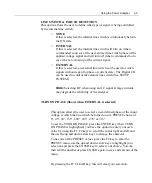
TURN ON PHASE (Shows when INTERNAL is selected)
This option allows the user to select a user-defined phase of the input
voltage at which the line switch be turned on or a PRESET choice of
0°, 45°, 90°, 135°, 180°, 225°, 270° or 315°.
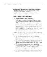
To set the TURN ON PHASE, press the ENTER key when TURN
ON PHASE is highlighted, you have the option to enter your own
value by using the F1, F2 keys to scroll the cursor right and left and
the use the up and down arrow keys to change the character.
To use one of the PRESET values, press the F4 key to enter the
PRESET menu, use the up and down arrow keys to highlight your
selection and press the ENTER key to select your choice. You can
then edit the number or press ENTER again to save and exit out of the
menu.
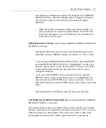
By pressing the F3 CLEAR key, this will clear your selection.
Содержание Xitron 2801
Страница 1: ...USER GUIDE 2801 2802 Advanced Single and Dual Channel Power Analyzers...
Страница 2: ...2 2801 2802 Power Analyzer User Guide...
Страница 10: ...10 2801 2802 Power Analyzer User Guide...
Страница 19: ...Functional Description 19 Voltage Input Attenuator Figure 2 Voltage Input Attenuator Block Diagram...
Страница 101: ...Printing Results 101 Figure 66 Configuration Printout...
Страница 102: ...102 2801 2802 Power Analyzer User Guide Figure 67 Waveform Channel 1 Real time...
Страница 103: ...Printing Results 103 Figure 68 Waveform Channe1 Distortion...
Страница 104: ...104 2801 2802 Power Analyzer User Guide Figure 69 History Chart VOLTS ACDC Trends View...
Страница 105: ...Printing Results 105 Figure 70 History Chart AMPS PERCENT THD Extents View...
Страница 106: ...106 2801 2802 Power Analyzer User Guide Figure 71 Harmonics Listing page 1...
Страница 107: ...Printing Results 107 Figure 72 Harmonics Listing page 2...
Страница 145: ...Sending Commands and Interrogatives 145...
Страница 147: ...Appendix A Physical Specifications 147...
Страница 153: ...Appendix B Measurement Specifications 153...

