


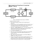


58
2801/2802 Power Analyzer User Guide
HIGH FREQ (>40Hz)
Configures the analyzer to make the optimal signal measurements at
frequencies higher than line frequency, in the range 40Hz to above
100kHz. The analyzer –
1) Synchronizes on the voltage waveform with frequencies in the range
of 40Hz to above 100kHz; and
2) Tracks input signals using no low-pass filtering.
Note:
When you enable autoranging and a downrange is required, the
analyzer downranges at the rate of 20ms per range. HIGH FREQ (>40Hz)
is the recommended selection when making high frequency measurements
or for line measurements where a large amount of high frequency signal
content is present.
10kHz -200kHz
Configures the analyzer to make optimal signal measurements at
frequencies in the range 10kHz to 200kHz. To accomplish this, the
analyzer –
1) Synchronizes on the voltage waveform with frequencies in the range
of 10kHz to 200kHz; and
2) Tracks the input signals using a fixed low-pass filter where the filter
corner frequency is set to maintain better than 5% accuracy at 10kHz.
Note:
When you enable autoranging and a downrange is required, the
analyzer downranges at the rate of 10ms per range. The 10kHz-200kHz
selection is recommended when making high frequency measurements.
The 10kHz -200kHz setting is not recommended for line measurements.
DC
Configures the analyzer to make optimal signal measurements at DC. To
accomplish this, the analyzer operates as follows.
1) When not configured for ripple measurements -
Measurements of DC and AC are made over 50ms periods. No harmonic
data is available. Frequency is not measured. Signals have a fixed-
corner, 4kHz, low-pass filter applied.
2)
When configured for ripple measurements –
All DC and non-harmonic AC measurements are made over the longer of
5ms (rounded upwards to the nearest integer number of cycles) or one
Содержание Xitron 2801
Страница 1: ...USER GUIDE 2801 2802 Advanced Single and Dual Channel Power Analyzers...
Страница 2: ...2 2801 2802 Power Analyzer User Guide...
Страница 10: ...10 2801 2802 Power Analyzer User Guide...
Страница 19: ...Functional Description 19 Voltage Input Attenuator Figure 2 Voltage Input Attenuator Block Diagram...
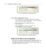
Страница 101: ...Printing Results 101 Figure 66 Configuration Printout...
Страница 102: ...102 2801 2802 Power Analyzer User Guide Figure 67 Waveform Channel 1 Real time...
Страница 103: ...Printing Results 103 Figure 68 Waveform Channe1 Distortion...
Страница 104: ...104 2801 2802 Power Analyzer User Guide Figure 69 History Chart VOLTS ACDC Trends View...
Страница 105: ...Printing Results 105 Figure 70 History Chart AMPS PERCENT THD Extents View...
Страница 106: ...106 2801 2802 Power Analyzer User Guide Figure 71 Harmonics Listing page 1...
Страница 107: ...Printing Results 107 Figure 72 Harmonics Listing page 2...
Страница 145: ...Sending Commands and Interrogatives 145...
Страница 147: ...Appendix A Physical Specifications 147...
Страница 153: ...Appendix B Measurement Specifications 153...


