Vitrek Xitron 2801 Скачать руководство пользователя страница 17


Functional Description 

17 

Functional Description 

This chapter describes the circuitry and interfaces of the 2801/2802 Power 
Analyzer.  

Theory of Operation 


OVERALL BLOCK DIAGRAM 


Figure 1. Overall Block Diagram 

Содержание Xitron 2801

Страница 1: ...USER GUIDE 2801 2802 Advanced Single and Dual Channel Power Analyzers...

Страница 2: ...2 2801 2802 Power Analyzer User Guide...

Страница 3: ...ctive as a result of misuse improper repair or abnormal conditions or operations repairs will be billed at cost Vitrek assumes no responsibility for its product being used in a hazardous or dangerous...

Страница 4: ...subject to change without notice The product s displays and manual text may be used or copied only in accordance with the terms of the license agreement XiTRON is a trademark of Vitrek All other trad...

Страница 5: ...________________________ 24 Digital I O __________________________________________________ 24 Ethernet____________________________________________________ 24 USING THE POWER ANALYZER _________________...

Страница 6: ...t Configuration ________________________ 56 Setting Up the Ch2 Measurement Configuration 2802 Only __________ 71 Setup System___________________________________________________ 71 Configuration Storag...

Страница 7: ...toring and Recalling Configurations________________________________ 111 IEEE488 Status Byte Commands __________________________________ 112 Commands which affect the measurement process ______________...

Страница 8: ...4 LINECONTROL Configures the Line Switch _____________________ 124 LINEPHASE Internal Line Switch Turn On Phase_________________ 124 INRUSHARNG Sets the A input Inrush Range ___________________ 125 IN...

Страница 9: ...Frequency Measurements ____________________________________ 149 Harmonic Analysis __________________________________________ 149 Result Averaging____________________________________________ 150 Input...

Страница 10: ...10 2801 2802 Power Analyzer User Guide...

Страница 11: ...___________ 34 Figure 12 Measuring a Power Source Method 2 _______________________ 35 Figure 13 Measuring a Load Method 1 ______________________________ 36 Figure 14 Measuring a Load Method 2 ________...

Страница 12: ..._____________________________________ 84 Figure 42 Rectified Normal ________________________________________ 84 Figure 43 Fundamental Normal ____________________________________ 85 Figure 44 Harmonics...

Страница 13: ..._____ 161 Figure 75 AC Voltage Autorange High Frequency ____________________ 162 Figure 76 AC Voltage Fixed Range High Frequency __________________ 163 Figure 77 AC Current Autorange Low Frequency____...

Страница 14: ...zer User Guide Figure 93 VAR vs Frequency _____________________________________ 180 Figure 94 Watts vs Frequency ____________________________________ 181 Figure 95 Power Factor vs Frequency___________...

Страница 15: ...alyzer for efficiency standby power or ENERGY STAR testing In addition to numerical results the 2801 2802 analyzer captures waveforms with true 512 point precision Results and waveforms can be display...

Страница 16: ...er frequency harmonics THD PF CF K Factor Triplens inrush distortion glitches and much more Integrated line switch and inrush waveforms Source or load measurements with wiring loss and voltage burden...

Страница 17: ...ctional Description 17 Functional Description This chapter describes the circuitry and interfaces of the 2801 2802 Power Analyzer Theory of Operation OVERALL BLOCK DIAGRAM Figure 1 Overall Block Diagr...

Страница 18: ...hen a single resistor fails to a short circuit b To reduce the voltage coefficient of the attenuator caused by self heating when high voltages are applied and c To ensure that the input can withstand...

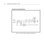
Страница 19: ...Functional Description 19 Voltage Input Attenuator Figure 2 Voltage Input Attenuator Block Diagram...

Страница 20: ...20 2801 2802 Power Analyzer User Guide Transducer Input Attenuator Figure 3 Transducer Input Attenuator Block Diagram...

Страница 21: ...f the turn on sequence when operating with AC voltages is accomplished by the MCU delaying turning on the TRIAC after being commanded to do so by the DSP by an amount commanded by the DSP from the act...

Страница 22: ...an the relay If the switch is used in high dV dT situations e g inductive loads then it may be required that the user add an external snubber circuit This circuitry cannot be included internally as it...

Страница 23: ...35 viewing area Keyboard Seven fixed purpose keys four softkeys IEEE488 Interface IEEE488 1 Certain commands conform to IEEE488 2 Addressing Single address user selectable via front panel between 0 a...

Страница 24: ...er language or supporting unformatted text transfers Printer must be directly connected to the 2802 hubs are not supported RS 232 RTS CTS hardware handshaking Also supports the DTR and DSR signals Bau...

Страница 25: ...the analyzer Using the front panel interface Rear panel connections Power testing Setting Up The power analyzer is made to sit on the bench The viewing angle can be optimized by adjusting the handle...

Страница 26: ...TION PROVIDED BY THE EQUIPMENT MAY BE IMPAIRED Using the Front Panel Interface Use the 2801 2802 front panel interface to select and setup the desired tests and to read the test results The interface...

Страница 27: ...g the Power Analyzer 27 Figure 7 2801 Front Panel Interface Detail Figure 8 2802 Front Panel Interface Detail The highlighted menu item will be initiated by pressing the ENTER key Figure 9 Sample Disp...

Страница 28: ...liseconds When turning it off the LED turns from green to yellow Use the and up and down arrow keys to scroll a highlight bar through options in a menu to bring up the various measurement results for...

Страница 29: ...MENU The PRINT key allows the user to print a full page of data reflecting the display results The formatting of the printout is either graphical or numerical tabulation The F1 F2 F3 and F4 keys are...

Страница 30: ...olation to the requirements of EN61010 This isolation is 100 tested to 4 5kV peak The V connections are fully isolated from the Internal Electronic Ground using transformer isolation to the requiremen...

Страница 31: ...other equivalent grounded output DC power supply then the ground is supplied via that power supply In these cases the user need not provide any additional ground connection to the product provided th...

Страница 32: ...tors Refer to Figure 10 The connectors used for testing measuring functions are along the midline of the instrument The connectors used for communications and control are along the bottom The ground t...

Страница 33: ...Using the Power Analyzer 33 Figure 10 Rear Connection Panel Power Line Connection Current Input T Connector Optional Line In Voltage Input Ground Terminal...

Страница 34: ...ce and the current and voltage measurement points should be kept as short as possible to avoid inductive and capacitive losses causing inaccuracies Optionally set Wiring Impedance to W1 W2 ohms Includ...

Страница 35: ...short as possible to avoid inductive and capacitive losses causing inaccuracies Optionally set Wiring Impedance to W1 W2 ohms The instrument will always automatically adjust for the internal shunt bu...

Страница 36: ...inductive and capacitive losses causing inaccuracies Optionally set Wiring Impedance to W1 W2 ohms The instrument will always automatically adjust for the internal shunt burden resistance if the chann...

Страница 37: ...tween the load and the current and voltage measurement points should be kept as short as possible to avoid inductive and capacitive losses causing inaccuracies Optionally set Wiring Impedance to W1 W2...

Страница 38: ...the source and the points at which the voltage is measured in the entered value for wiring impedance Set V Burden Compensation to YES If the current measurement terminals of the 2801 or the wire thro...

Страница 39: ...D IN A MANNER NOT SPECIFIED BY VITREK THE PROTECTION PROVIDED BY THE EQUIPMENT MAY BE IMPAIRED WARNING IT IS RECOMMENDED THAT THE PROTECTIVE CONDUCTOR TERMINAL IS CONNECTED TO EARTH GROUND WHEN THE SI...

Страница 40: ...he current and voltage measurement points should be kept as short as possible to avoid inductive and capacitive losses causing inaccuracies Optionally set Wiring Impedance to W1 W2 ohms Include all wi...

Страница 41: ...as possible to avoid inductive and capacitive losses causing inaccuracies Optionally set Wiring Impedance to W1 W2 ohms The instrument will always automatically adjust for the internal shunt burden re...

Страница 42: ...ve and capacitive losses causing inaccuracies Optionally set Wiring Impedance to W1 W2 ohms The instrument will always automatically adjust for the internal shunt burden resistance if the channel is s...

Страница 43: ...e load and the current and voltage measurement points should be kept as short as possible to avoid inductive and capacitive losses causing inaccuracies Optionally set Wiring Impedance to W1 W2 ohms In...

Страница 44: ...Wiring Loss V A W1ohms W2ohms W1ohms W2ohms Figure 21 Measuring a Power Source and Load Method 1 Two Ind Chnls Configure the channels as follows This connection method is suitable for most Independen...

Страница 45: ...e Set V Burden Compensation to YES If the current measurement terminals are reversed then set Reverse Current to YES otherwise set to NO If the voltage measurement terminals are reversed then set Reve...

Страница 46: ...els as follows Select 3P 3W from the Getting Started Menu The 2802 will provide the following results Two of the actual measured voltages X Z and Y Z The Voltage Difference Y X Two of the actual measu...

Страница 47: ...source and the points at which the voltage is measured in the entered value for wiring impedance Set V Burden Compensation to YES If the current measurement terminals of the 2802 or the wire through t...

Страница 48: ...BNC Type connection The following diagram shows the recommended method for wiring up an external current transducer to the 2801 or 2802 Figure 24 External Transducer Test Connections To setup the uni...

Страница 49: ...LOWING STEPS Press the F2 key twice Press the DEL key once The decimal point will disappear and the screen will show 10 A Press the F2 key once the screen will show 100 A Press the F2 key one more tim...

Страница 50: ...form the DC ZERO procedure This is performed after making the connections and allowing the external transducer to settle after application of its power 3 Particularly when operating at low current lev...

Страница 51: ...TING STARTED SETUP MEASUREMENTS SETUP SYSTEM CONFIGURATION STORAGE PERFORM DC ZERO DIAGNOSTICS ABOUT 2802 GETTING STARTED CHANNEL CONFIGURATION SETUP INPUT MEASUREMENTS SETUP OUTPUT MEASUREMENTS SETUP...

Страница 52: ...d to configure the 2801 2802 We recommend selecting the appropriate choice that corresponds to your application when using the power analyzer for the first time To initiate the Getting Started setup 1...

Страница 53: ...2802 Only The second item listed is CHANNEL CONFIGURATION this is used to set how the channels will be used within the application Note There is no need to select one of these options if you had prev...

Страница 54: ...hoices will vary depending on which GETTING STARTED or CHANNEL CONFIGURATION has been selected Once in the setup menu the selections are listed in the order that they come up on the analyzer display I...

Страница 55: ...n is setup for LINE LINE async LINE HF then the menu choice is SETUP INPUT MEASUREMENTS SETUP OUTPUT MEASUREMENTS If the application is setup for DUAL LINE async DUAL HF then the menu choice is 2802 D...

Страница 56: ...the down arrow key to highlight SETUP Ch1 MEASUREMENTS 5 Press the ENTER key to enter into the SETUP Ch1 MEASUREMENTS as shown in Figure 27 Figure 28 Measurement Configuration Screen Setting Up the M...

Страница 57: ...is menu item contains the following seven setup selections LINE FREQ 1kHz Configures the analyzer to make optimal signal measurements at line frequencies in the 40 to 1000Hz range To accomplish this t...

Страница 58: ...ronizes on the voltage waveform with frequencies in the range of 10kHz to 200kHz and 2 Tracks the input signals using a fixed low pass filter where the filter corner frequency is set to maintain bette...

Страница 59: ...ENT below Note This USER SET selection is not recommended for inexperienced users LOW FREQ 0 5 20Hz Configures the analyzer to make optimal signal measurements at frequencies less than line frequency...

Страница 60: ...TION menu HF FILTER TYPE SYNC SOURCE MIN FUNDAMENTAL MAX FUNDAMENTAL MAX HARMONIC DOWNRANGE DELAY The following paragraphs define the above options HF FILTER TYPE NONE ADAPTIVE CUTOFF OR FIXED CUTOFF...

Страница 61: ...e number of harmonics measurable MAX HARMONIC This sets the range of Harmonics that will be reported back There are two choices with in the menu SET MIN and SET MAX DOWNRANGE DELAY This entry gives yo...

Страница 62: ...selected current signal When auto range has been selected the actual selected range being used is displayed in parentheses after AUTO AUTO 65A 20A 6 5A 2A 0 65A 300mA 100mA 30mA 10mA Transducer AUTO 1...

Страница 63: ...symbol Press the ENTER key when finished Note You can press the CLEAR F3 key to start over or clear the screen The INPUT scale is set first when the ENTER key is pushed the CT RATIO OUT screen will th...

Страница 64: ...ugh very small there is a finite current flowing between the voltage terminals of the analyzer Depending on the wiring method this current may flow through the current measuring device internal shunt...

Страница 65: ...SYSTEM Note Selecting DC when using an AC signal at large currents may degrade the reliability of the analyzer TURN ON PHASE Shows when INTERNAL is selected This option allows the user to select a us...

Страница 66: ...will use the line switch as the trigger to capture data for the INRUSH and STARTUP screens The following guidelines can be used to setup the appropriate combination for triggering the INRUSH and STAR...

Страница 67: ...when INRUSH DETECT LEVEL is highlighted You have the option to enter your own value by using the F1 F2 keys to scroll the cursor right and left and the use the up and down arrow keys to change the cha...

Страница 68: ...s as follows this filtering applies to all measurements MEASUREMENT TYPE LINE Uses an Adaptive HF Cutoff filter with an upper cutoff 5 down of the lower of 60kHz or twice the maximum measured harmonic...

Страница 69: ...trigger or show results on the INRUSH and STARTUP graph screens The Startup Chart is not user settable The STARTUP chart runs until the first of the following occurs 1 The chart is full typically abo...

Страница 70: ...lects the signal on which the unit will trigger when enabled The Menu choices are as follows NONE Trigger is disabled Vpeak Unit will trigger on the voltage peak Vglitch Unit will trigger on a voltage...

Страница 71: ...e Ch2 Measurement Configuration 2802 Only There are four selections in the Ch2 MEASUREMENT CONFIGURATION menu The following section defines each of the selections and the associated submenu options av...

Страница 72: ...settings to determine the best one mid point is 5 6 or 7 Select OFF for the backlight only if there is sufficient external light to read the display DIGITAL I 0 The following are the available config...

Страница 73: ...down Use the F1 and F2 softkeys to scroll left and right The F3 softkey moves back one month and F4 moves forward one month Press ENTER when done TIME Select the correct time in the default format Us...

Страница 74: ...ration changes highlight SAVE press ENTER scroll to the configuration location in which you want to save your configuration and press ENTER Figure 31 LOAD SAVE Main Menu Screen LOAD To LOAD a previous...

Страница 75: ...on Screen Perform DC Zero To initiate a DC ZERO press the MENU key Use the arrow keys up or down to highlight PERFORM DC ZERO Press the ENTER key and follow the prompts Figure 34 DC Zero Screen NOTE T...

Страница 76: ...tion of the LINE SWITCH key which is disabled while in this menu The KEYPAD TEST is used to verify that the front panel keys are operational When a key is pressed the key name will appear on the scree...

Страница 77: ...Using the Power Analyzer 77 Figure 36 Performance Screen About The ABOUT screen displays the current firmware revisions and the serial number of the unit Figure 37 About Screen...

Страница 78: ...UREMENT TYPE LINE FREQ 1kHz VOLTAGE INPUT AUTO CURRENT INPUT DIRECT A INPUT CURRENT RANGE AUTO STRICT RANGING NO CURRENT SCALING DISABLED MEASURE LOAD WIRING COMPENSATION NO COMPENSATE V BURDEN NO REV...

Страница 79: ...eans of a command issued via a control interface Note that this is not necessarily the state of the internal line switch Line Off A command initiated by pressing the front panel LINE ON OFF key when t...

Страница 80: ...quencies above 1kHz then the Line Switch must be set to the DISABLED state otherwise damage could be caused to the line switch in the long term 2 Only use the Line Switch for switching DC or AC with f...

Страница 81: ...the one used when not in the Inrush Period Inrush Waveform The voltage and current waveforms collected during the entire Inrush Period These waveforms are always collected during the Inrush Period wh...

Страница 82: ...relates with ACDC and Normal The F4 label showing RUN is an option Shown below is a display on HOLD where pressing F4 will continue updating the data displayed a Display Screens In the Numerics screen...

Страница 83: ...Figure 39 ACDC Inrush c Integrated Figure 40 ACDC Integrated d Integrated Average e Integrated Maximum f Integrated Minimum 2 AC rms a Normal b Inrush c Integrated d Integrated Average e Integrated M...

Страница 84: ...Normal Figure 41 DC Normal b Inrush c Integrated d Integrated Average e Integrated Maximum f Integrated Minimum 4 Rectified a Normal Figure 42 Rectified Normal b Inrush c Integrated d Integrated Aver...

Страница 85: ...a Normal Figure 43 Fundamental Normal b Integrated c Integrated Average d Integrated Maximum e Integrated Minimum f Load 6 Harmonics a Normal Figure 44 Harmonics Normal 7 DC Charge Discharge a Integra...

Страница 86: ...ii Harmonics Bar Charts 1 Volts a Percent Log b Percent Linear c Absolute Log d Absolute Linear 2 Amps a Percent Log b Percent Linear c Absolute Log d Absolute Linear Figure 47 Harmonics Log in Bar Ch...

Страница 87: ...ute Use F2 and F3 to scroll from the Fundamental Harmonic to the 100th Figure 48 Harmonics Absolute in List Form 2 Percent 3 Phase iv Waveforms 1 Real time Figure 49 Real time Waveform 2 Distortion Fi...

Страница 88: ...Startup and Inrush Charts are disabled Any data previously captured is maintained in the 2801 2802 as long as power is turned on and the user does not clear the chart Line Switch Disabled and Inrush D...

Страница 89: ...itch has been turned on by the user Note that the current must be below the Inrush detection level for at least 20ms before the 2802 will allow a new chart to be started If the current is not below th...

Страница 90: ...tion point When in the inspect mode the user can use the ZOOM OUT F3 softkey to ZOOM back out a level at a time or can use the FULL SPAN F4 key to exit back to the normal viewing screen The reference...

Страница 91: ...is shown as a blank spot in the chart the relative timing of all data is always accurate within the resolution limits of the chart The date and time at which the chart was last started is saved as th...

Страница 92: ...ht end of the scale shows the most recent data and the left end value of the x axis is fixed at the time at which the data collection was started Figure 52 History of Amps ACDC Trend in Full View Figu...

Страница 93: ...r DOWN arrow keys to scroll through the choices and press the ENTER key to select the following are the available choices VOLTS AMPS WATTS VA VAR PF FREQUENCY TEMPERATURE The TYPE of data to be displa...

Страница 94: ...cal time resolution of 1 cycle or 0 1 of the pre configured startup chart period whichever is larger The Startup period is factory set to approximately 4 minutes Data is collected over this time at fu...

Страница 95: ...Display Screens 95 Figure 57 Startup in Full View Trend Figure 58 Startup in Full View Extents Figure 59 Startup Partial Extents Figure 60 Startup Partial Extents...

Страница 96: ...or DOWN arrow keys to scroll through the choices and press the ENTER key to select the following are the available choices VOLTS AMPS WATTS VA VAR PF FREQUENCY The TYPE of data to be displayed can be...

Страница 97: ...ensure that no ranges occur during this period of time Figure 62 Range Change The date time at which the chart was started is saved as the reference date time for Inrush charts note that this is the s...

Страница 98: ...ing is a list of available data for the INRUSH charts The data to be displayed is selected by pressing the F1 key which will enter you into the INRUSH CHART DATA menu Press the ENTER key to view the a...

Страница 99: ...sults display screens Every printout includes Descriptive title of the data Configuration selections Current date month day year Calibrated date Time in hours minutes seconds Elapsed time Vitrek 2801...

Страница 100: ...ts amps and power waveforms will print together if a graphical print is selected If a text only printer is selected then volts and amps will print together Voltage and current Waveforms for PEAK DIST...

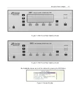
Страница 101: ...Printing Results 101 Figure 66 Configuration Printout...

Страница 102: ...102 2801 2802 Power Analyzer User Guide Figure 67 Waveform Channel 1 Real time...

Страница 103: ...Printing Results 103 Figure 68 Waveform Channe1 Distortion...

Страница 104: ...104 2801 2802 Power Analyzer User Guide Figure 69 History Chart VOLTS ACDC Trends View...

Страница 105: ...Printing Results 105 Figure 70 History Chart AMPS PERCENT THD Extents View...

Страница 106: ...106 2801 2802 Power Analyzer User Guide Figure 71 Harmonics Listing page 1...

Страница 107: ...Printing Results 107 Figure 72 Harmonics Listing page 2...

Страница 108: ...ust send the character to the unit or you will not get a reply Operating using Multiple Interfaces All three interfaces IEEE488 USB and RS232 operate in an independent manner They each have their own...

Страница 109: ...rement result response data when next read via the IEEE488 interface Remote Local Operation Any interface can command that the front panel user be locked out from making changes This does not lock out...

Страница 110: ...aring the measurement result responses Identifying the Instrument The user can send the IDN interrogative via any interface The response to this is of the following format XITRON 2801 0 v2 00 v2 00 v1...

Страница 111: ...digit corresponding to the format as used in the commands above TIMEFORMAT 0 sets that all times are in 12 hour format TIMEFORMAT 1 sets that all times are in 24 hour format TIMEFORMAT queries the pre...

Страница 112: ...gative queries the state of the RUN HOLD front panel control 0 is returned if the 2801 2 is presently in HOLD 1 is retuned if it is presently in RUN This is for the state of channel 2 integration when...

Страница 113: ...ation INRUSH queries the present INRUSH setting CLR INTEGRATION this command clears any integration data collected If an integration is running it continues to run after this command If an integration...

Страница 114: ...her than possibly starting collection this command does not affect any integrated measurement results CONT INTEGRATION CH2 this command continues the integration of measurement results for channel 2 w...

Страница 115: ...RO commands the 2801 2 to abort any DC Zero operation in progress DC ZERO STATUS queries the 2801 2 regarding the status of any DC Zero in progress A zero response indicates that no DC zero is in prog...

Страница 116: ...or A may be used in place of CH1 and OUT or B may be used in place of CH2 Setting channel 2 data when configured for synchronous channel operation is allowed but has no affect until configured for as...

Страница 117: ...7 1 second result averaging 8 2 5 second result averaging 9 5 second result averaging 10 10 second result averaging 11 20 second result averaging 12 1 minute result averaging RESULTAVG queries the pr...

Страница 118: ...eries the present FILTERTYPE setting FILTERFREQ HF Filter Cutoff Frequency This is only effective when MSRTYPE 4 and FILTERTYPE 2 FILTERFREQ value sets the fixed HF filter cutoff frequency to value in...

Страница 119: ...that set by value integer will be measured MAXHARMS 0 disables harmonics measurements and waveform collection and capture MAXHARMS queries the present MAXHARMS setting GENDNRANGEDLY User Set Minimum...

Страница 120: ...Voltage Input Range VRANGE value sets the V input range to be used to that associated with the value as shown below 0 Autorange 1 850V 2 450V 3 135V 4 50V 5 20V VRANGE queries the present actual range...

Страница 121: ...2A 5 0 65A 6 300mA 7 100mA 8 30mA 9 10mA ARANGE queries the present actual range selection TRANGE Select a Current Input Range Transducer Input Only This is only effective when AINPUT 2 TRANGE value...

Страница 122: ...by the SHUNTRATIO2 value Effectively the SHUNTRATIO1 value is the input current level to the external CT which corresponds to an output current level from that CT given by the SHUNTRATIO2 value SHUNTR...

Страница 123: ...esent WIRINGCOMP setting WIRINGLOSS Sets the Wiring Loss Impedance Value Effects Channel 1 or None Only This is only effective when WIRINGCOMP 1 WIRINGLOSS value sets the wire impedance level to value...

Страница 124: ...ent Measurement Polarities REVERSEA 0 Currents A or T input do not have their polarity reversed REVERSEA 1 All Current A or T input Measurements have their polarity reversed REVERSEA queries the prese...

Страница 125: ...50ms following turning on the internal line switch The same values as used for TRANGE are used with the exception of the 0 value which is not allowed INRUSHTRNG queries the present INRUSHTRNG settings...

Страница 126: ...etting TRIGVOLTS Sets the Voltage for Waveform Capture Triggering This is ineffective if harmonics are not being measured for any reason or if WAVETRIG 0 3 or 4 TRIGVOLTS value sets the peak glitch vo...

Страница 127: ...ote For RS232 after sending the READ command you must send the character to the unit or you will not get a reply Keyword Fields Where Keyword defines the general data being requested Fields contains n...

Страница 128: ...ction Type Specification defaults to normal INRUSH INTEG CHARGE DISCHARGE INTEG AVG or AVERAGE INTEG MAX or HIGHEST INTEG MIN or LOWEST Logarithmically Scaled default is linear DB Extents or Median Va...

Страница 129: ...chnl or A HIPK chnl ACDC A HIPK chnl AC A LOPK chnl or A LOPK chnl ACDC A LOPK chnl AC A PKPK chnl A RECT chnl FREQ chnl LOADR chnl FUND LOADR chnl DC LOADZ chnl FUND LOADZ chnl DC LOADX chnl or LOADX...

Страница 130: ...ver all harmonics between harmonic start thru harmonic end inclusive using a step value of step A HRNG chnl start end step A THD chnl start end step A KFACT chnl start end TRIPLENS start end EVEN TRIP...

Страница 131: ...chnl npoints EXTENTS V CAP GLITCH chnl npoints MEDIAN A WAVE chnl npoints EXTENTS A WAVE chnl npoints MEDIAN A DIST chnl npoints EXTENTS A DIST chnl npoints MEDIAN A CAP chnl npoints EXTENTS A CAP chn...

Страница 132: ...AC MEDIAN LIMITS npoints t_start t_span A PK HIST chnl AC EXTENTS TRENDS npoints t_start t_span A PK HIST chnl AC MEDIAN TRENDS npoints t_start t_span A THD HIST chnl EXTENTS LIMITS npoints t_start t_...

Страница 133: ...AC EXTENTS TRENDS npoints t_start t_span VAR HIST chnl AC MEDIAN TRENDS npoints t_start t_span VAR HIST chnl FUND EXTENTS LIMITS npoints t_start t_span VAR HIST chnl FUND MEDIAN LIMITS npoints t_start...

Страница 134: ...span W HIST chnl ACDC MEDIAN TRENDS npoints t_start t_span W HIST chnl AC EXTENTS LIMITS npoints t_start t_span W HIST chnl AC MEDIAN LIMITS npoints t_start t_span W HIST chnl AC EXTENTS TRENDS npoint...

Страница 135: ...points t_start t_span A PK STARTUP chnl ACDC MEDIAN LIMITS npoints t_start t_span A PK STARTUP chnl ACDC EXTENTS TRENDS npoints t_start t_span A PK STARTUP chnl ACDC MEDIAN TRENDS npoints t_start t_sp...

Страница 136: ...MEDIAN LIMITS npoints t_start t_span VA STARTUP chnl FUND EXTENTS TRENDS npoints t_start t_span VA STARTUP chnl FUND MEDIAN TRENDS npoints t_start t_span VAR STARTUP chnl AC EXTENTS LIMITS npoints t_s...

Страница 137: ...EXTENTS LIMITS npoints t_start t_span V WYE STARTUP chnl MEDIAN LIMITS npoints t_start t_span V WYE STARTUP chnl EXTENTS TRENDS npoints t_start t_span V WYE STARTUP chnl MEDIAN TRENDS npoints t_start...

Страница 138: ...r A LOPK chnl ACDC INRUSH A LOPK chnl AC INRUSH A PKPK chnl INRUSH A RECT chnl INRUSH FREQ chnl INRUSH PF chnl INRUSH or PF chnl ACDC INRUSH PF chnl AC INRUSH PF chnl FUND INRUSH DPF chnl INRUSH VA ch...

Страница 139: ...AMPS chnl ACDC INTEG AMPS chnl AC INTEG AMPS chnl DC INTEG AMPS chnl FUND INTEG A RECT chnl INTEG VA chnl INTEG or VA chnl ACDC INTEG VA chnl AC INTEG VA chnl DC INTEG VA chnl FUND INTEG VAR chnl INT...

Страница 140: ...G VOLTS chnl FUND INTEG AVG WATTS chnl INTEG AVG or WATTS chnl ACDC INTEG AVG WATTS chnl AC INTEG AVG WATTS chnl DC INTEG AVG WATTS chnl FUND INTEG AVG Measurement Extents during Integration These all...

Страница 141: ...CDC INTEG MAX V CF chnl AC INTEG MAX V FF chnl INTEG MAX V PK chnl INTEG MAX or V PK chnl ACDC INTEG MAX V PK chnl AC INTEG MAX V HIPK chnl INTEG MAX or V HIPK chnl ACDC INTEG MAX V HIPK chnl AC INTEG...

Страница 142: ...IN VAR chnl INTEG MIN or VAR chnl AC INTEG MIN VAR chnl FUND INTEG MIN VOLTS chnl INTEG MIN or VOLTS chnl ACDC INTEG MIN VOLTS chnl AC INTEG MIN VOLTS chnl DC INTEG MIN VOLTS chnl FUND INTEG MIN V CF...

Страница 143: ...e of day DATE Returns the present date INT TIME chnl Returns the integration time in hours CHARGE TIME chnl Returns the charge time in floating point hours DISCHARGE TIME chnl Returns the discharge ti...

Страница 144: ...span of the full inrush waveform chart in floating point seconds INRUSH TIME Returns the start time of day for the inrush waveform chart INRUSH DATE Returns the start date for the inrush waveform char...

Страница 145: ...Sending Commands and Interrogatives 145...

Страница 146: ...55 C 95 RH non condensing Storage 20 C to 70 C non condensing Altitude Equivalent Atmospheric pressures and air densities from 1000ft below sea level to 15000ft above sea level Warm Up Specifications...

Страница 147: ...Appendix A Physical Specifications 147...

Страница 148: ...ranges each cycle Ranging Commanded range changes take less than 5ms Input Filtering When user set for low pass filtering the user entered frequency is that for 5 attenuation otherwise accuracy is va...

Страница 149: ...and the user has selected no default frequency DC Input Offset Compensation The user may select to use the present DC signals as compensation for future DC measurements This compensates for both inter...

Страница 150: ...The DC voltage and current measurement results are also integrated separately depending on the polarity of the DC current and are made available as the Charge and Discharge integrated results History...

Страница 151: ...waveform with a peak value or with a non fundamental component is found which is higher than a user set trigger level or that previously encountered as specified by the user Inrush Waveforms The volta...

Страница 152: ...2802 Power Analyzer User Guide Turn On Phase Within 1 20us of the commanded turn on phase if applicable On Voltage Loss 0 1 after the defined inrush period 3Vpk during the defined inrush period Off Le...

Страница 153: ...Appendix B Measurement Specifications 153...

Страница 154: ...ernal Offsets of up to 20V may be compensated for on any DC Offset range compensation is performed at the input prior to range selection Compensation When enabled the input may be polarity reversed an...

Страница 155: ...2V 0 1V F kHz per 500V applied to Voltage Lo terminal relative to ground Temperature Effects Add 0 007 of reading per C when operating more than 5 C from the calibration temperature no effect on relat...

Страница 156: ...kHz and unfiltered Rectified Accuracy 1 5x RMS accuracy Form Factor Accuracy 0 5x RMS accuracy as a percentage of 1 0 Peak Accuracy Filtered 20kHz RMS accuracy 50uA 0 01 of peak range Unfiltered RMS a...

Страница 157: ...nabled the input may be polarity reversed and or adjusted to compensate for the current caused by the measured voltage across the Voltage Input Burden RMS Accuracy As shown in the charts for AC AC DC...

Страница 158: ...Power Factor VA Specifications Accuracy Voltage Accuracy Current Accuracy See charts for Current Accuracy for each current input method Temperature Effects Add the Voltage temperature effects and the...

Страница 159: ...VAR Error of VA and 0 01 of VA See charts for VAR error and for Power Accuracy for each current input method When combining of VAR and of VA use of VAR of VA v 1 DPF 2 or of VA of VAR v 1 DPF 2 DPF is...

Страница 160: ...year Specification AC Voltage Autorange CF 1 5 Line or LF Measurements 0 01 0 10 1 00 10 00 0 1 1 10 100 1000 Input Level Vrms Accuracy reading Line Measurements Add 0 05 per KHz LF Measurements Add 0...

Страница 161: ...d Range Any CF Line or LF Measurements 0 01 0 10 1 00 10 00 0 1 1 10 100 1000 Input Level Vrms Accuracy reading 850V Range 450V Range 135V Range 50V Range 20V Range Line Measurements Add 0 05 per KHz...

Страница 162: ...cation AC Voltage Autorange CF 1 5 HF Measurements 0 01 0 10 1 00 10 00 0 1 1 10 100 1000 Input Level Vrms Accuracy reading Below 100KHz Add 0 02 per KHz 100 200KHz Add 0 04 per KHz tested but not gua...

Страница 163: ...ge Any CF HF Measurements 0 01 0 10 1 00 10 00 0 1 1 10 100 1000 Input Level Vrms Accuracy reading 850V Range 450V Range 135V Range 50V Range 20V Range Below 100KHz Add 0 02 per KHz 100 200KHz Add 0 0...

Страница 164: ...ation AC Current Autorange CF 2 5 Line or LF Measurements 0 01 0 10 1 00 10 00 0 0001 0 001 0 01 0 1 1 10 100 Input Level Arms Accuracy reading Line Measurements Add 0 05 per KHz LF Measurements Add 0...

Страница 165: ...surements 0 01 0 10 1 00 10 00 0 0001 0 001 0 01 0 1 1 10 100 Input Level Arms Accuracy reading 65A Range 20A Range 6 5A Range 2A Range 0 65A Range 300mA Range 100mA Range 30mA Range 10mA Range Line M...

Страница 166: ...AC Current Autorange CF 2 5 HF Measurements 0 01 0 10 1 00 10 00 0 0001 0 001 0 01 0 1 1 10 100 Input Level Arms Accuracy reading Below 100KHz Add 0 02 per KHz 100 200KHz Add 0 04 per KHz tested but...

Страница 167: ...1 0 10 1 00 10 00 0 0001 0 001 0 01 0 1 1 10 100 Input Level Arms Accuracy reading 65A Range 20A Range 6 5A Range 2A Range 0 65A Range 300mA Range 100mA Range 30mA Range 10mA Range Below 100KHz Add 0...

Страница 168: ...168 2801 2802 Power Analyzer User Guide 1 year Specification DC Voltage Autorange 0 01 0 10 1 00 10 00 0 1 1 10 100 1000 Input Level Vdc Accuracy reading Figure 81 DC Voltage Autorange...

Страница 169: ...t Specifications 169 1 year Specification DC Voltage Fixed Range 0 01 0 10 1 00 10 00 0 1 1 10 100 1000 Input Level Vdc Accuracy reading 850V Range 450V Range 135V Range 50V Range 20V Range Figure 82...

Страница 170: ...170 2801 2802 Power Analyzer User Guide 1 year Specification DC Current Autorange 0 01 0 10 1 00 10 00 0 0001 0 001 0 01 0 1 1 10 100 Input Level Arms Accuracy reading Figure 83 DC Current Autorange...

Страница 171: ...pecification DC Current Fixed Range 0 01 0 10 1 00 10 00 0 0001 0 001 0 01 0 1 1 10 100 Input Level Adc Accuracy reading 65A Range 20A Range 6 5A Range 2A Range 0 65A Range 300mA Range 100mA Range 30m...

Страница 172: ...Transdcuer Input Autorange CF 1 5 Line or LF Measurements 0 01 0 10 1 00 10 00 0 001 0 01 0 1 1 10 100 Input Level Vrms Accuracy reading Line Measurements Add 0 05 per KHz LF Measurements Add 0 3 per...

Страница 173: ...ge Any CF Line or LF Measurements 0 01 0 10 1 00 10 00 0 001 0 01 0 1 1 10 100 Input Level Vrms Accuracy reading 15V Range 5V Range 1 5V Range 0 5V Range 0 15V Range Line Measurements Add 0 05 per KHz...

Страница 174: ...Transducer Input Autorange CF 2 5 HF Measurements 0 01 0 10 1 00 10 00 0 001 0 01 0 1 1 10 100 Input Level Vrms Accuracy reading Below 100KHz Add 0 02 per KHz 100 200KHz Add 0 3 per KHz tested but no...

Страница 175: ...ge Any CF HF Measurements 0 01 0 10 1 00 10 00 0 001 0 01 0 1 1 10 100 Input Level Vrms Accuracy reading 15V Range 5V Range 1 5V Range 0 5V Range 0 15V Range Below 100KHz Add 0 02 per KHz 100 200KHz A...

Страница 176: ...802 Power Analyzer User Guide 1 year Specification DC Voltage Transducer Input Autorange 0 01 0 10 1 00 10 00 0 001 0 01 0 1 1 10 100 Input Level Vrms Accuracy reading Figure 89 DC Voltage Transducer...

Страница 177: ...177 1 year Specification DC Voltage Transducer Input Fixed Range 0 01 0 10 1 00 10 00 0 001 0 01 0 1 1 10 100 Input Level Vdc Accuracy reading 15V Range 5V Range 1 5V Range 0 5V Range 0 15V Range Figu...

Страница 178: ...F 2 5 Any Measurements 0 01 0 10 1 00 10 00 0 0001 0 001 0 01 0 1 1 10 100 Input Level Arms Accuracy reading HF Measurements Add 0 04 per KHz below 100KHz HF Measurements Add 0 1 per KHz 100 200KHz Li...

Страница 179: ...01 0 001 0 01 0 1 1 10 100 Input Level Arms Accuracy reading 65A Range 20A Range 6 5A Range 2A Range 0 65A Range 300mA Range 100mA Range 30mA Range 10mA Range HF Measurements Add 0 04 per KHz below 10...

Страница 180: ...Power Analyzer User Guide VAR Error vs Frequency at selected DPF Values 0 001 0 010 0 100 1 000 10 000 10 100 1000 10000 100000 Frequency Hz VAR Error of VA 0 999 0 975 0 8 0 6 0 4 0 0 2 Figure 93 VAR...

Страница 181: ...arget Specifications 181 Watts Error vs Frequency at selected DPF Values 0 001 0 010 0 100 1 000 10 000 10 100 1000 10000 100000 Frequency Hz Watts Error of VA 0 999 0 975 0 9 0 8 0 6 0 4 0 Figure 94...

Страница 182: ...User Guide Power Factor Error vs Frequency at selected DPF Values 0 00001 0 00010 0 00100 0 01000 0 10000 10 100 1000 10000 100000 Frequency Hz Power Factor Error 0 999 0 975 0 9 0 8 0 6 0 4 0 Figure...

Отзывы: