


Using the Power Analyzer
61
signal content of the applied voltage signal. To measure the
fundamental in the applied voltage signal, enter both a maximum
fundamental frequency and a trigger level.
FROM CURRENT
This is similar to the FROM VOLTAGE selection, however,
uses the selected current input signal as the source of
fundamental frequency measurements. Most effective when used
where the voltage signal has complex frequency content. (e.g.
Use FROM CURRENT with switch-mode motor drives.)
•
MIN FUNDAMENTAL
This option sets the lowest frequency to which the analyzer will
synchronize and sets the rate at which downranging occurs (if
ENABLED). Selecting an extremely low value makes auto-ranging
very slow, as the minimum down range interval is one period of this
settable frequency.
•
MAX FUNDAMENTAL
This option sets the highest frequency to which the analyzer will
synchronize and determines the number of harmonics measurable.
•
MAX HARMONIC
This sets the range of Harmonics that will be reported back. There are
two choices with in the menu, SET MIN and SET MAX.
•
DOWNRANGE DELAY
This entry gives you control of the minimum time between successive
downranges when using autoranging. Typically set to one period of
the expected lowest frequency of any signal content (e.g. 20ms for
most measurements). However there may be cases where the applied
signal has considerable sub-fundamental signal content (e.g. a
computer may draw a varying current with a period of a few hundred
milliseconds, or a high frequency signal may have significant line
modulation). Note that to stop the analyzer from continuously
autoranging to accommodate these fast, regular, changes in signal, the
entry for the DOWNRANGE DELAY can be extended.
Note:
Typically the analyzer can downrange up to two ranges per interval,
setting an overly lengthy MIN DOWNRANGE TIME can slow down
autoranging when traversing from the highest to the lowest range.
RANGING & SCALING
This menu item contains the following four setup selections –
Содержание Xitron 2801
Страница 1: ...USER GUIDE 2801 2802 Advanced Single and Dual Channel Power Analyzers...
Страница 2: ...2 2801 2802 Power Analyzer User Guide...
Страница 10: ...10 2801 2802 Power Analyzer User Guide...
Страница 19: ...Functional Description 19 Voltage Input Attenuator Figure 2 Voltage Input Attenuator Block Diagram...
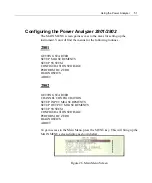
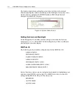
Страница 101: ...Printing Results 101 Figure 66 Configuration Printout...
Страница 102: ...102 2801 2802 Power Analyzer User Guide Figure 67 Waveform Channel 1 Real time...
Страница 103: ...Printing Results 103 Figure 68 Waveform Channe1 Distortion...
Страница 104: ...104 2801 2802 Power Analyzer User Guide Figure 69 History Chart VOLTS ACDC Trends View...
Страница 105: ...Printing Results 105 Figure 70 History Chart AMPS PERCENT THD Extents View...
Страница 106: ...106 2801 2802 Power Analyzer User Guide Figure 71 Harmonics Listing page 1...
Страница 107: ...Printing Results 107 Figure 72 Harmonics Listing page 2...
Страница 145: ...Sending Commands and Interrogatives 145...
Страница 147: ...Appendix A Physical Specifications 147...
Страница 153: ...Appendix B Measurement Specifications 153...


