


95x Series Operating Manual - May 17, 2022
Page
127
of
155
If the 95x is power cycled, then it will power up with no active session; the user should employ timeouts to detect
that the 95x has become off-line and restart the session.
If a session is inactive for more than 1 minute then the 95x will allow a session to be initiated from a different
source, automatically closing the inactive session. This prevents a potential lockup if the user does not close an
active session properly.
STATUS REGISTERS
There are several status registers associated with the 95x interfaces.
STB AND SRE REGISTERS
These are specifically used to show the status of and control the assertion of the GPIB SRQ signal. The value of the
STB register is logically ANDed with the value of the SRE register; if the result is non-zero then the GPIB SRQ line is
asserted. The STB register is read by the GPIB interface when a serial poll bus command is performed.
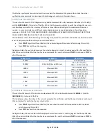
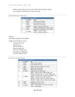
These are common to all interfaces. They are 8-bit registers (i.e., has values from 0 to 255). Each bit is defined as
follows
–
•
Bit 0, decimal value 1, binary value 00000001
–
set if a high voltage is currently present on the HV
terminal. The value of this status bit is “dynamic” –
i.e., its value can change without user interaction.
•
Bit 1, decimal value 2, binary value 00000010
–
set when a test step dwell period is completed, cleared
when read, when a test sequence is started, when a different test sequence is selected, or when reset.
•
Bit 2, decimal value 4, binary value 00000100
–
set if a test sequence is currently being performed. The
value of this status bit is “dynamic” –
i.e., its value can change without user interaction.
•
Bit 3, decimal value 8, binary value 00001000
–
set when a test sequence is completed, cleared when
read, when a test sequence is started, when a different test sequence is selected, or when reset.
•
Bit 4, decimal value 16, binary value 00010000
–
set when a test failure has been detected, cleared when
read, when a test sequence is started, when a different test sequence is selected, or when reset.
•
Bit 5, decimal value 32, binary value 00100000
–
set when an ARC current over limit has been detected,
cleared when read, when a test sequence is started, when a different test sequence is selected, or when
reset.
•
Bit 6, decimal value 64, binary value 01000000
–
as defined by IEEE488.1, set if the 95x is asserting the
SRQ line, otherwise it is cleared. Always zero for the SRE register.
•
Bit 7, decimal value 128, binary value 10000000
–
not used, always 0.
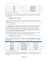
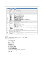
OPC REGISTER
This is separate within each interface. This is an 8-bit register (i.e., has values from 0 to 255). All of the bits in this
register are cleared when read by the user. Each bit is defined as follows
–
•
Bit 0, decimal value 1, binary value 00000001
–
set when a command set is decoded without error.
•
Bit 1, decimal value 2, binary value 00000010
–
set when a command is decoded with a field count error.
•
Bit 2, decimal value 4, binary value 00000100
–
set when a command is decoded with an internal memory
error.
•
Bit 3, decimal value 8, binary value 00001000
–
set when a command is decoded with a field syntax or
data range error.
•
Bit 4, decimal value 16, binary value 00010000
–
set when a command is decoded with a compatibility
error (e.g., this 95x variant is incapable of performing the requested operation).


