95x Series Operating Manual - May 17, 2022
Page
108
of
155
(TESTING), and the TESTING output should be configured to be ACTIVE LO to cause the indicator to be illuminated
when testing.
Note
–
if instead the user wished to have a High Voltage warning indicator, then this is similarly accomplished by
using the HV DETECT signal instead of the TESTING signal.
Example 2 -
It is desired to use an external mechanical switch to start a sequence rather than the 95x front panel START button.
The test sequence will be manually selected at the 95x front panel. The switch will be momentarily actuated to
start a sequence.
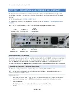
In this case the mechanical switch should be connected between DIO connector pin 3 (COMMON) and pin 4
(START). Assuming that the switch is to be closed to start a sequence, the user should configure the START input
as ACTIVE LO and the SEQUENCE inputs as IGNORE.
Example 3 -
This is the same as example 2, but the external switch will be held closed during the test sequence. If the switch is
released during the sequence, then it will be aborted.
In this case the mechanical switch should be connected between DIO connector pin 3 (COMMON) and both pins 4
(START) and 5 (ABORT). The user should configure the START input as ACTIVE LO, the ABORT input as ACTIVE HI as
and the SEQUENCE inputs as IGNORE.
Example 4 -
This is the same as example 2 but the user wishes to always run sequence #3 when the external start switch is
activated. The user will not need to select a test sequence from the front panel.
In this case the mechanical switch should be connected between DIO connector pin 3 (COMMON) and pin 4
(START), and also pins 10 and 11 (SEQUENCE 4 and 8) should be connected directly to pin 3 (COMMON).
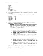
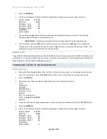
Assuming that the switch is closed to start a sequence, the user should configure the START input as ACTIVE LO
and the SEQUENCE inputs as ACTIVE HI. Note, the connections to the SEQUENCE inputs will select sequence #3
since SEQUENCE 1 and 2 are open circuit (so will be high = active) while SEQUENCE 4 and 8 are grounded (so will
be low = inactive).
Example 5
–
The user wishes to use a mechanical safety hood enclosure over the DUT, which must be maintained closed during
testing for safety reasons. A magnetic switch is mounted on the hood which is closed when the hood is in position.
In this case the magnetic switch is used with the INTERLOCK capability of the 95x and should be connected
between DIO connector pin 3 (COMMON) and pin 6 (INTERLOCK).
If the safety hood is opened while the 95x is producing high (i.e., unsafe) voltages then the test will be immediately
aborted. However, the user can still open the hood (e.g., to make wiring changes to the DUT) during the test
sequence as long as they are made while there are no unsafe voltages present (e.g., a HOLD step could be
programmed in the sequence to allow the user to make the changes and then press the START button to continue
testing).

