


95x Series Operating Manual - May 17, 2022
Page
114
of
155
•
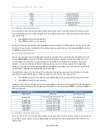
The above step is repeated at levels of 500V then 100Vdc. The 95x specification is ±0.35% at 500Vdc and
±0.75% at 100Vdc.
•
The user is now prompted to provide a source of 50mAdc (equipment #4 listed above) between the
SENSE-
(+) and
GND/GUARD
(-) terminals of the 95x. Apply the connections to the 95x terminals ensuring
the connections are to the correct terminals and with the correct polarity, and then set the source to
provide the current. When the current is correctly applied press
START
to continue the procedure. The
user is now shown the difference in calibration at 50mAdc between this calibration and the last
calibration of the 95x. If the change is acceptable then press
START
to accept it and continue the
procedure, otherwise abort the calibration by pressing
STOP
. NOTE
–
the 95x specification at this level is
±0.25%. The 95x display will show FAILED if the calibration is out of range for calibration, not if the
change is beyond the specification.
•
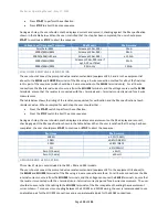
The above step is repeated at levels of 10mA, 1mA then 100uAdc.
•
The user is now prompted to connect a 4-wire 10K
Ω
resistance (equipment #5 listed above) to the 95x
terminals. The 95x internal current source is from the
SOURCE
terminals, and the voltage sense uses the
SENSE
terminals, ensure that the resistor is connected with the + terminals and
–
terminals correctly
paired for a 4-wire measurement. When the 10K
Ω
resistance is correctly applied press
START
to continue
the procedure. The user is now shown the difference in calibration at 10K
Ω
between this calibration and
the last calibration of the 95x. If the change is acceptable then press
START
to accept it and continue the
procedure, otherwise abort the calibration by pressing
STOP
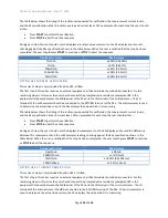
. NOTE
–
the 95x specification at this level is
±0.8%. The 95x display will show FAILED if the calibration is out of range for calibration, not if the change
is beyond the specification.
•
The user is now prompted to connect a 4-wire 10
Ω
resistance (equipment #6 listed above) to the 95x
terminals. The 95x internal current source is from the
SOURCE
terminals, and the voltage sense uses the
SENSE
terminals, ensure that the resistor is connected with the + terminals and
–
terminals correctly
paired for a 4-wire measurement. When the 10
Ω
resistance is correctly applied press
START
to continue
the procedure. The user is now shown the difference in calibration at 10
Ω
between this calibration and
the last calibration of the 95x. If the change is acceptable then press
START
to accept it and continue the
procedure, otherwise abort the calibration by pressing
STOP
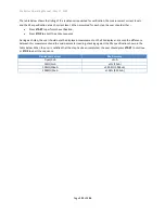
. NOTE
–
the 95x specification at this level is
±0.8%. The 95x display will show FAILED if the calibration is out of range for calibration, not if the change
is beyond the specification.
•
The user is now prompted to connect a 4-wire 1
Ω
impedance (equipment #7 listed above) to the 95x
terminals. The 95x internal current source is from the
SOURCE
terminals, and the voltage sense uses the
SENSE
terminals, ensure that the resistor is connected with the + terminals and
–
terminals correctly
paired for a 4-wire measurement. The use of short leads is recommended, and steps should be taken to
reduce the potential for coupling between the SOURCE and SENSE wires. Ideally, the SOURCE wires
should be a twisted pair, and the SENSE wires a separate twisted pair spaced away from the SOURCE pair.
When the 1
Ω
impedance is correctly applied press
START
to continue the procedure.
•
The user is now prompted for the actual, calibrated value of the 1
Ω
. The user should enter the correct
value using the numeric keys and then press
ENTER
. The user is now shown the difference in calibration at
1
Ω
between this calibration and the last calibration of the 95x. If the change is acceptable then press
START
to accept it and continue the procedure, otherwise abort the calibration by pressing
STOP
. NOTE
–
the 95x specification at this level is ±1.5%. The 95x display will show FAILED if the calibration is out of
range for calibration, not if the change is beyond the specification.
•
(Option HSS or HSS-2 only). The user is now prompted to attach a 1Mohm resistor and a milli-ammeter
(equipment #8 listed above). The resistor should be connected between the HV terminal of the 95x and


