18
Cables/leads and hydraulic lines
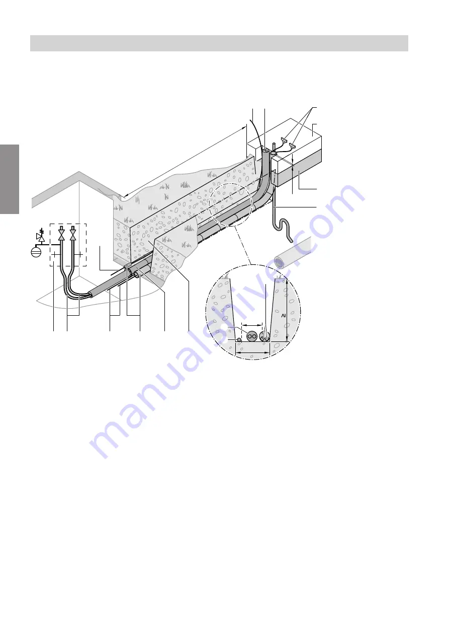
Laying the lines underground and routing in through the exterior wall
M
N
M
Q
P
F
R
O
O
M
N
400
N
K
O
N
P
T
S
U
B
20
900
Fig. 10
B
Concrete foundation (300 mm thick) consisting of:
■
Concrete slab C25/30, BSt 500 S and M
■
Reinforcement with all-round Q 257 A wire mesh
C
KG conduit DN 100 for power cable (on site)
D
KG conduit DN 100 for connecting cables to the
heat pump control unit (on site):
Control cable 230 V~, LV lead < 42 V
E
Hydraulic connection set (accessories): Connec-
tion lines for heating water flow and heating water
return
F
Condensate drain DN 40 (on site)
K
Frost protection (compacted crushed stone,
e.g. 0 to 32/56 mm); thickness of layer subject to
local requirements and building regulations
M
Flexible power cable to compressor/fan (on site)
N
2 connecting cables inside DN 100 KG conduit (on
site), fully wired (5, 15 or 30 m):
■
Control cable
230 V~
■
LV lead
< 42 V
Note
The maximum lead length is 30 m. Extensions
are not permissible.
O
Hydraulic connection lines (heating water flow and
heating water return)
P
Underground channel
Q
Wall duct with expanding mortar (on site) for
hydraulic connection line
R
Moisture-proof and waterproof wall ducts (on site)
S
Drain & fill facility with shut-off valve (for draining
with compressed air)
T
Expansion vessel with safety assembly (accesso-
ries)
U
Clearance, house wall
—
foundations:
■
Max. clearance depends on length of connecting
cables and hydraulic connection lines:
Max. 23 m
■
Maintain the minimum clearance to other objects
(> 1.5 m) when siting.
Heating water connection (hydraulic connection
lines
O
)
Use the hydraulic connection set (accessory). The
connection set is fully prepared in different lengths.
The flow and return lines are flexible and have 2 adap-
tors each. The lines are located inside a common ther-
mal insulation.
Preparing for installation
External heat pump
(cont.)
5692878
Installation
Содержание Vitocal 350-A AWHI 351.A14
Страница 22: ...22 Fig 13 Installation sequence Type AWHI 351 A only Fitting the supplied floor mat 5692878 Installation ...
Страница 26: ...26 3x 8 9 3x 3x 3x Fig 17 Installation sequence Fitting the outer panels cont 5692878 Installation ...
Страница 27: ...27 10 3x 3x 2x 11 Fig 18 Installation sequence Fitting the outer panels cont 5692878 Installation ...
Страница 30: ...30 Type AWHI 351 A 1 Fig 22 Installation sequence Siting the heat pump cont 5692878 Installation ...
Страница 66: ...66 Fitting the front panel 1 2 Fig 64 Installation sequence Closing the heat pump cont 5692878 Installation ...
Страница 82: ...82 Troubleshooting Repairs cont 5692878 Maintenance ...
Страница 101: ...101 Parts list type AWHI 351 A Heat pump module cont 5692878 Components ...
Страница 104: ...104 Parts list type AWHI 351 A Base frame cont 5692878 Components ...
Страница 110: ...110 Silencer hood 0001 0002 0001 Fig 86 Parts list type AWHO 351 A Casing cont 5692878 Components ...
Страница 114: ...114 0007 0007 0003 0005 0003 0002 0001 0006 0005 0008 Fig 88 Parts list type AWHO 351 A Air module 5692878 Components ...
Страница 125: ...125 Parts list type AWHO 351 A Heat pump module cont 5692878 Components ...


