


51
E
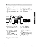
Only type BW 2150, BW 2180,
BW 2250, WW 2200, WW 2250,
WW 2300:
EEV PCB 2 for compressor 2 (stage
2)
F
EEV PCB 1 for compressor 1 (stage
1)
G
Main PCB with extension PCB
H
F3 Fuse 6.3 A (slow)
K
Controller and sensor PCB
L
X24 Slot for LON communication
module
M
X31 Coding card slot
Terminal area, front
N
O
P
R
S
T
U V
W
N
Only type BW 2150, BW 2180,
BW 2250, WW 2200, WW 2250,
WW 2300:
Fuse/MCB, power circuit, compres-
sor 2
O
Only type BW 2150, BW 2180,
BW 2250, WW 2200, WW 2250,
WW 2300:
Contactor, compressor 2
P
Only type BW 2150, BW 2180,
BW 2250, WW 2200, WW 2250,
WW 2300:
Soft starter, compressor 2
R
Fuse/MCB, power circuit, compres-
sor 1
S
Contactor, compressor 1
T
Soft starter, compressor 1
U
Fuse/MCB, power circuit, system
components (consumer at terminal
strip
D
, see separate "connection
and wiring diagram" sheet 13
"13F2")
V
Fuse/MCB, control circuit (see sep-
arate "connection and wiring dia-
gram" sheet 13 "13F6")
W
Message and safety connections
(safety chain) with distribution ter-
minal
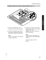
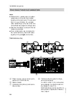
Installation sequence
Overview of electrical connections
(cont.)
5772 458 GB
Installation


