52
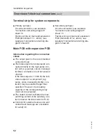
Terminal strip for system components
■ Primary pump(s):
On-site connection, see separate
"connection and wiring diagram"
sheet 13.
Factory wiring on main and expansion
PCB (terminals 211.1, 224.2), see
separate "connection and wiring dia-
gram" sheet 20.
■ Secondary pump(s):
On-site connection, see separate
"connection and wiring diagram"
sheet 13.
Factory wiring on main and expansion
PCB (terminals 211.2, 224.3), see
separate "connection and wiring dia-
gram" sheet 20.
Main PCB with expansion PCB
Information regarding the connection
values
■ The output given is the recommended
connected load.
■ The total output of all components con-
nected directly to the heat pump con-
trol unit (e.g. pumps, valves, message
facilities, contactors) must not exceed
1000 W.
If the total output is < 1000 W, the indi-
vidual output of a component (e.g.
pump, valve, messaging facility, con-
tactor) may be selected larger than
specified. However, the breaking
capacity of the corresponding relay
must not be exceeded.
■ The stated current indicates the max.
switching current of the switching con-
tact (observe the total current of 5 A).
■ Controls for external heat source and
central fault message are unsuitable
for safety LV.
Installation sequence
Overview of electrical connections
(cont.)
5772 458 GB


