


50
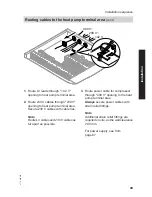
Note
■ Route 230 V~ cables and LV cables
separately and bundle them tightly
together at the terminals. This ensures
that, in case of failure, for example
when detaching a wire, the wires can-
not drift into the adjacent voltage area.
■ Strip the insulation as close to the ter-
minals as possible.
■ If two components are connected to
the same terminal, press both wires
together into a single wire ferrule.
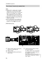
Terminal area, top
A
C
D
E
F
H
L
K
M
G
B
F3
A
Power supply, power circuit (com-
pressor) 3 x 400 V/50 Hz
B
Mains isolator
C
Contactors for primary and secon-
dary pumps
D
Terminal strip for system compo-
nents (consumers)
3 x 400 V~/230 V~ (for connection,
see separate "connection and wir-
ing diagram" sheet 13).
Switched phase can be used for on-
site system components. Observe
max. output.
Installation sequence
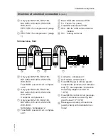
Overview of electrical connections
5772 458 GB


