


60
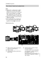
Message and safety connections (safety chain) with distribution
terminal
LP1
LP1
X3 LP1 LP1 LP1 X1
LP1 LP1
St.
K1 K1 K1
K1
X3
K2 K2 K2
K2
X3
X1
X3 X3 X2 X3
X3
X3 X3 X3 X3 X3
16 N
X3 X2
LP1 LP1
116 116 116 X2 X3
116 116 116 X2 X3
16 N
X3 X2
LP1 LP1
PE
13
16
3 2 7
PE
6 9
X1.PE
11
6 4 2
4
16
6 4 2 16 4
5 3 1 N 3
5 3 1 N 3
PE
12
N 4 14 6 6 5 5 8
10
220.3
1
K2 STB
2
220.2
Distribution terminal
St.
223.2
223.1
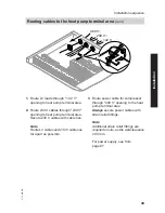
■ Set the required parameters during
commissioning; see from page 79.
■ Connections, see separate "connec-
tion and wiring diagram" sheet 13,
sheet 21.
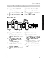
Signal and safety connections
Terminals
Function
Explanation
PE/X1.
Earth conductor
Terminals for earth conductor of
all
asso-
ciated system components.
LP1.X2.N
Neutral conductor
Terminals for the neutral conductor of the
heat pump control unit.
Connected at the factory.
LP1.X3.16
Phase L1
Control unit power supply.
Connected at the factory.
Installation sequence
Overview of electrical connections
(cont.)
5772 458 GB


