


36
Type BW 190 to BW 2240 and WW 1125 to WW 2300
Hydraulic installation scheme
W
30
36
35
33
34
--2/F6--
--
--2/224.6--
WW
KW
32
--2/224.6--
X
W
Heat pump interface
X
Interface to the solar thermal sys-
tem or the external heat source
KW Cold water
WW DHW
Required equipment
Pos.
Designation
eP
DHW cylinder
eW
Cylinder temperature sensor
eE
Cylinder primary pump (DHW side, fail-safe)
eR
Plate heat exchanger
eT
Flow limiter
eZ
Motorised 2-way valve, normally closed
Note
Permissible cylinder temperatures:
■ Top section:
Max. 50 °C
■ Average cylinder temperature:
45 °C
Size the plate heat exchanger
eR
in
accordance with the technical guide.
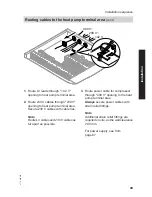
Preparing for installation
DHW heating
5772 458 GB


