


94
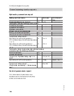
Checking fuses
Fuses/MCB in the front terminal area,
see page 51:
■ Power circuit fuse/MCB
Compressor 1 and 2 (separate "con-
nection and wiring diagram" sheet 11/
sheet 12 "11F2"/"12F2"):
Subject to output of heat pump/com-
pressor, see chapter "Specification"
■ Fuse/MCB, power circuit, system
components (see separate "connec-
tion and wiring diagram" sheet 13
"13F2")
16 A
■ Fuse/MCB, control circuit (see sepa-
rate "connection and wiring diagram"
sheet 13 "13F6"):
6.0 A (slow), 250 V~
Fuses/MCB in the top terminal area, see
page 50:
■ Fuse/MCB F3 on main PCB:
6.3 A (slow), 250 V~
Max. power loss ≤ 2.5 W
Danger
Contact with 'live' components
can lead to serious injury from
electric current.
Before working on the equip-
ment, always ensure that
the
power circuit is also at zero
volt.
Removing the fuse does
not
switch the power circuit to zero
volt
.
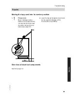
Appliance too noisy
Possible causes:
■ Transport bracket not removed.
■ Doors at the front not properly closed
(turn quadrant key as far as it will go).
■ Hydraulic line touches the heat pump
casing.
■ Hydraulic line not connected free of
load and torque stress.
■ Silencer elements for Victaulic cou-
plings missing.
Troubleshooting
Repairs
(cont.)
5772 458 GB


