background image

150

Extension EA1

A1

PCB

F1

Fuse

DE1

Digital input 1

DE2

Digital input 2

DE3

Digital input 3

0 – 10 V 0 - 10 V input

Power supply

 A

Power supply for additional
accessories

aBJ

Central fault message/feed
pump/DHW circulation pump
(potential-free)

aVG

KM BUS

Function description

External extensions (accessories)

 (cont.)

5623 520 GB

Содержание Series B2HA 40

Страница 1: ...instructions for contractors VIESMANN Vitodens 200 W Type B2HA 125 and 150 kW Wall mounted gas condensing boiler Natural gas and LPG version For applicability see the last page VITODENS 200 W 5623 520 GB 6 2012 Please keep safe ...

Страница 2: ...f accidents all legal instructions regarding envi ronmental protection the Code of Practice of relevant trade associations all current safety regulations as defined by DIN EN DVGW TRGI TRF VDE and all locally applicable standards Gas Safety Installation Use Regu lations the appropriate Building Regulation either the Building regulations the Building Regulation Scotland Building Regulations Norther...

Страница 3: ...static dis charges Touch earthed objects such as heating or water pipes to dis charge static loads Repair work Please note Repairing components which ful fil a safety function can compro mise the safe operation of your heating system Replace faulty components only with original Viessmann spare parts Ancillary components spare and wearing parts Please note Spare and wearing parts which have not bee...

Страница 4: ...ructions Commissioning inspection maintenance Steps commissioning inspection and maintenance 28 Further details regarding the individual steps 30 Code 1 Calling up coding level 1 66 General group 1 67 Boiler group 2 70 DHW group 3 70 Solar group 4 71 Heating circuit 1 heating circuit 2 heating circuit 3 group 5 73 Code 2 Calling up coding level 2 80 General group 1 81 Boiler group 2 90 DHW group 3...

Страница 5: ...trol unit 160 Designs Connection and wiring diagram internal connections 162 Connection and wiring diagram external connections 163 Parts lists Ordering parts 165 Overview of the assemblies 166 Casing assembly 167 Heat cell assembly 168 Burner assembly 169 Hydraulic assembly 169 Control unit assembly 170 Miscellaneous 171 Commissioning service reports 173 Specification 174 Certificates Declaration...

Страница 6: ...those countries specified on the type plate For deliveries to alternative countries an approved contractor on his own initiative must arrange individual approval in accordance with the law of the land Multi boiler system In connection with the installation of a multi boiler system observe the installation instructions of the multi boiler system accessories Preparing for installation Product inform...

Страница 7: ...es 165 5 165 5 923 1440 95 689 278 905 600 P 40 200 855 1975 1950 E L M O K H N A B C G D F 70 70 195 A Safety valve B Expansion vessel connection G1 C Boiler flow 7 54 mm D Cylinder flow 7 42 mm E Gas connection R 1 F Cylinder return 7 42 mm Preparing for installation Preparing for installation 5623 520 GB Installation ...

Страница 8: ...s boiler protection IP X4 D is approved for installation in wet rooms inside safety zone 1 according to DIN VDE 0100 Germany if hosed water can be prevented Observe DIN VDE 0100 or local regula tions 1 Prepare the water connections Thor oughly flush the heating system 2 Prepare gas connection to TRGI or local regulations 3 Prepare the electrical connections Power cable NYM J 3 x 1 5 mm2 max fuse 1...

Страница 9: ...g cushions and keep them safe They are used as a support during levelling 2 Undo two screws on the underside 3 Remove front panel 4 Push packing cushions onto the underside of the boiler Installation sequence Fitting the boiler and making connections 5623 520 GB Installation ...

Страница 10: ...lled holes for attaching lifting gear 5 Please note To prevent damage do not level boiler without packing cushions Level boiler with pallet Installation sequence Fitting the boiler and making connections cont 5623 520 GB ...

Страница 11: ...her con struction materials use fixings that are suitable for 145 kg loads 1975 Ø 12 B C D A 2 1 A Reference point boiler top edge B Installation template included with the boiler C Top edge finished floor D Recommendation Installation sequence Fitting the boiler and making connections cont 5623 520 GB Installation ...

Страница 12: ...12 Hooking the boiler into the wall mounting bracket and levelling it 1 3 2x 3 2 Installation sequence Fitting the boiler and making connections cont 5623 520 GB ...

Страница 13: ... may escape when undo ing the locking caps Flue gas connection Note The labels System certificate and Sko berne GmbH flue system enclosed with the technical documentation may only be used in conjunction with the Viessmann flue system made by Skoberne Installation sequence Heating water side connection 5623 520 GB Installation ...

Страница 14: ...ct flue pipe or flue ventilation air pipe Flue system installation instruc tions Condensate connection Connect the condensate hose with a constant fall and a pipe vent to the public sewage system or to a neutralising sys tem Installation sequence Flue gas connection cont 5623 520 GB ...

Страница 15: ...age Remove residues of the leak detec tion agent after testing Please note Excessive test pressure may damage the boiler and the gas valve Max test pressure 150 mbar Where higher pressure is required for tightness tests disconnect the boiler and the gas valves from the gas sup ply pipe undo the fitting 3 Vent the gas line Conversion to other gas types Service instructions Opening the control unit ...

Страница 16: ...16 3 2 2x 1 4 4x 5 Installation sequence Opening the control unit casing cont 5623 520 GB ...

Страница 17: ...mp or boiler circuit pump C Vitotrol 100 UTDB only for constant temperature control When making this connection remove jumper between 1 and L D Vitotrol 100 UTA only for constant temperature control or Vitotrol 100 UTDB RF radio clock receiver When making this connection remove jumper between 1 and L Installation sequence Electrical connections 5623 520 GB Installation ...

Страница 18: ...ories Cylinder temperature sensor part of the DHW cylinder connection set aVG KM BUS subscriber accessory Vitotrol 200A or 300A remote control Vitocom 100 Extension kit for one heating cir cuit with mixer Solar control module type SM1 Vitosolic Extension AM1 Extension EA1 Wireless base station Information on connecting accessories When connecting accessories observe the separate installation instr...

Страница 19: ... heating circuit without mixer A1 39 1 Circulation pump for cylinder heating delivered condi tion 39 2 External demand via switching contact Connection options Extension EA1 accessory see sepa rate installation instructions Plug lH Connection Please note Live contacts lead to short cir cuits or phase failure The external connection must be floating Installation sequence Electrical connections cont...

Страница 20: ...coding address 06 in group Boiler 2 Codes Plug lH Extension EA1 4b 1 in group General 1 Set 3A DE1 3b DE2 or 3C DE3 in group General 1 to 2 Select effect of the function on the relevant heating circuit pump in coding address d7 in group Heating circuit 5 Select effect of the function on the circulation pump for cylinder heating in coding address 5F in group DHW 3 External demand via 0 10 V input C...

Страница 21: ... value 100 C External blocking via switching contact Connection options Plug lH Extension EA1 accessory see sepa rate installation instructions Please note Live contacts lead to short cir cuits or phase failure The external connection must be floating Installation sequence Electrical connections cont 5623 520 GB Installation ...

Страница 22: ... note When blocked there is no frost protection for the heating system Codes Plug lH Extension EA1 4b 2 in group General 1 Set 3A DE1 3b DE2 or 3C DE3 in group General 1 to 3 or 4 Select effect of the function on the heating circuit pump in coding address d6 in group Heating circuit 5 Select effect of the function on the circulation pump for cylinder heating in coding address 5E in group DHW 3 Out...

Страница 23: ...essories at plug lH 230 V Where the boiler is installed in a wet area the connection of accessories to the power supply must not be carried out at the control unit The power supply connection for accessories can be made immediately at the control unit if the boiler is installed outside wet areas This connection is switched directly with the ON OFF switch of the control unit If the total system cur...

Страница 24: ...2 C Extension kit for heating circuit with mixer M3 D Extension AM1 EA1 and or solar control module type SM1 E ON OFF switch If the current flowing to the connected working parts e g circulation pumps is higher than the safety level of the acces sory the output concerned should only be used to control an on site relay Accessories Internal fuse protection Extension kit for heat ing circuit with mix...

Страница 25: ...or in the power cable which simultaneously separates all non earthed conductors from the mains with contact separation of at least 3 mm Furthermore we recommend instal ling an AC DC sensitive RCD RCD class B for DC fault currents that can occur with energy efficient equipment Max fuse rating 16 A Installation sequence Electrical connections cont 5623 520 GB Installation ...

Страница 26: ...ded 5 A Low voltage connections B 230 V connections C Internal extension D Main PCB E Communication module F Cable grommet for power cable Plugs for connecting the cylinder temperature sensor to the cable har ness Remove the existing cable grommet when using larger cross sections up to 7 14 mm Secure the cable with the cable grommet plugged into the lower casing section F black Installation sequen...

Страница 27: ...ntrol unit support Note The programming unit can also be housed in a wall mounting base acces sory near the boiler Wall mounting base installation instructions Installation sequence Closing the control unit casing and inserting the programming unit 5623 520 GB Installation ...

Страница 28: ...ide for leaks 9 Checking the power supply 10 Designating heating circuits only for weather compensated control units 36 11 Checking the gas type 36 12 Gas type conversion only for operation with LPG 37 13 Function sequence and possible faults 37 14 Checking the static and supply pressure 39 15 Maximum output setting 41 16 Checking the balanced flue system for tightness annular gap check 42 17 Remo...

Страница 29: ... 27 Checking all gas equipment for tightness at operating pressure 49 28 Checking combustion quality 49 29 Checking the flue system for unrestricted flow and tightness 30 Checking the external LPG safety valve if installed 31 Matching the control unit to the heating system 51 32 Adjusting the heating curves only for weather compensated control units 58 33 Connecting the control unit to the LON 61 ...

Страница 30: ...30 Opening the boiler 2x 2 1 4 3 Commissioning inspection maintenance Further details regarding the individual steps 5623 520 GB ...

Страница 31: ... hardness in excess of the following values must be softened e g with a small soft ening system for heating water Total permissible hardness of the fill and top up water Total heating output Specific system volume kW 20 l kW 20 l kW to 50 l kW 50 l kW 50 3 0 mol m3 16 8 dH 2 0 mol m3 11 2 dH 0 02 mol m3 0 11 dH 50 to 200 2 0 mol m3 11 2 dH 1 5 mol m3 8 4 dH 0 02 mol m3 0 11 dH 200 to 600 1 5 mol m...

Страница 32: ...rmiss operating pressure 6 bar 5 Close boiler drain fill valve A Selecting the language if necessary only for weather com pensated control units At the commissioning stage the display is in German factory setting Extended menu 1 å 2 Settings 3 Language Sprache Cesky CZ Deutsch DE Dansk English DK GB Wählen mit Ø ç 4 Set the required language with Commissioning inspection maintenance Further detail...

Страница 33: ...3 Time Date 4 Set current time and date Note When time and date have been set the control unit automatically checks the function of the flue gas temperature sen sor The display shows Test flue gas temp sensor and Active For further details regarding the flue gas temperature sensor test see page 139 Commissioning inspection maintenance Further details regarding the individual steps cont 5623 520 GB...

Страница 34: ...to top tap B and connect to a drain 4 Open taps A and B and vent at mains pressure purge until no sound of escaping air can be heard and no more air bubbles are visible 5 Close taps A and B open the shut off valves on the heating water side 6 Remove hoses again Commissioning inspection maintenance Further details regarding the individual steps cont 5623 520 GB ...

Страница 35: ... Venting Venting function is enabled 4 Ending venting function Press OK or ä Service menu 1 Press OK and å simultaneously for approx 4 s 2 Select 5 with Ú and confirm with OK ON flashes 3 Activate the venting function with OK EL on is shown constantly 4 Ending venting function Press ä Filling the siphon with water E F C D A B 1 Pull off cap A downwards 2 Undo hose B 3 Undo union nut C and pull off...

Страница 36: ...r that adjusts the burner for optimum combustion in accordance with the prevailing gas qual ity Consequently for natural gas there is no adjustment required across the entire Wobbe index range The boiler can be operated in the Wobbe index range 9 5 to 15 2 kWh m3 34 2 to 54 7 MJ m3 Convert the burner for operation with LPG see Gas type conversion on page 37 1 Determine the gas type and Wobbe index...

Страница 37: ...In code 11 select value 9 End service functions 4 Open the gas shut off valve 5 Affix label G 31 included with the technical documentation in a clearly visible position near the gas train on the cover panel Function sequence and possible faults Display Measures Control unit is sues a heat de mand no Increase set value and ensure heat is drawn off yes Fan starts no After approx 51 s fault F9 Check ...

Страница 38: ...onisation current builds Symbol A no Fault EE Check the ionisa tion electrode ad justment and the gas line for air locks yes Burner in opera tion no Stops below the set boiler water temperature and restarts immedi ately Check the flue gas system for tight ness flue gas re circulation check the gas flow pres sure Commissioning inspection maintenance Further details regarding the individual steps co...

Страница 39: ...ed Press reset button R For further details regarding faults see page 117 Checking the static and supply pressure Danger CO build up as a result of incor rect burner adjustment can have serious health implications Carry out a CO test before and after work on gas appliances Operation with LPG Flush the LPG tank twice during com missioning or replacement Vent the tank and gas supply line thoroughly ...

Страница 40: ...airlocks in the gas line After approx 5 s press R to reset the burner 6 Check the supply flow pressure Set values Natural gas 20 mbar LPG 50 mbar Note Use a suitable measuring device with a resolution of at least 0 1 mbar to measure the supply pressure 7 Record the actual value in the service report Take the action shown in the follow ing table 8 Shut down the boiler close the gas shut off valve r...

Страница 41: ...0 mbar for natu ral gas or 50 mbar for LPG Notify your gas supply utility or LPG supplier Maximum output setting The maximum output for heating oper ation can be limited The limit is set via the modulation range The max adjust able output is limited upwards by the boiler coding card Weather compensated control unit 1 Press OK and å simultaneously for approx 4 s 2 Service functions 3 Max output 4 C...

Страница 42: ...as inspector is not applicable We recommend that your heating engi neer carries out a simple leak tightness test during the commissioning of your system For this it would be sufficient to check the CO2 or O2 concentration in the combustion air at the annular gap of the balanced flue pipe The flue pipe is deemed to be gas tight if the CO2 concentration in the combus tion air is no higher than 0 2 o...

Страница 43: ... Unlock control unit A and pivot for wards 4 Remove cover panel B 5 Pull cables from fan motor C gas train D ignition unit E and ionisa tion electrode F 6 Undo gas supply pipe fitting G 7 Undo six screws H and remove the burner Please note To prevent damage never touch the mesh of the burner gauze assembly Commissioning inspection maintenance Further details regarding the individual steps cont 562...

Страница 44: ...E F D 4x A 1 Remove electrodes A 2 Undo six retaining clips B on ther mal insulation ring C and then remove thermal insulation ring C 3 Undo four Torx screws D and remove burner gauze assembly E with burner gauze assembly gasket F Commissioning inspection maintenance Further details regarding the individual steps cont 5623 520 GB ...

Страница 45: ...Torque 4 0 Nm 5 Refit thermal insulation ring C and electrodes A Checking the flue gas non return device B A 1 Undo three screws and remove fan A 2 Remove flue gas non return device B Commissioning inspection maintenance Further details regarding the individual steps cont 5623 520 GB Service ...

Страница 46: ...Check the electrodes for wear and contamination 2 Clean the electrodes with a small brush not with a wire brush or sand paper Please note Do not damage the mesh of the burner gauze assembly 3 Check the electrode gaps If the gaps are not as specified or the electrodes are damaged replace the electrodes together with new gaskets and adjust them as required Tighten the elec trode fixing screws with 3...

Страница 47: ...n the combustion chamber 2 If necessary spray slightly acidic chloride free cleaning agents based on phosphoric acid onto heat exchanger A and let the solution soak in for at least 20 min 3 Thoroughly flush heat exchanger A with water 4 Install the burner and torque the screws diagonally with 8 5 Nm 5 Fit the gas supply pipe with a new gasket Torque fittings with 15 Nm Commissioning inspection mai...

Страница 48: ...p C downwards 2 Undo hose D 3 Undo union nut E and pull siphon F downwards 4 Clean siphon F 5 Check that the condensate can drain freely to the public sewage system 6 Fill siphon F with water and reas semble 7 Refit hose D 8 Push on cap C from below Checking the diaphragm expansion vessel and system pressure Note Carry out this test on a cold system 1 Drain the system or close the cap valve on the...

Страница 49: ...oller automatically ensures optimum combus tion quality During commissioning maintenance only the combustion val ues need to be checked For this meas ure the CO content plus the CO2 or O2 content For a description of the elec tronic combustion controller functions see page 160 Note Operate the appliance with uncontami nated combustion air to prevent operat ing faults and damage CO content The CO c...

Страница 50: ...t Constant temperature control unit Service menu 1 Press OK and å simultaneously for approx 4 s 2 Actuator test 3 Select the lower heating output Select Base load OFF Then Base load ON appears and the burner op erates at its lower heating output 4 Select the upper heating output Select Full load OFF Then Full load ON appears and the burner op erates at its upper heating output 5 Ending output sele...

Страница 51: ... circuit without mixer A1 with without DHW heating with low loss header 1 2 3 4 6 5 9 qP 8 7 ID 4605139_1103_02 1 Vitodens 200 W 2 Outside temperature sensor only for weather compensated control units or Vitotrol 100 only for constant tem perature control units 3 Boiler circuit pump 4 Circulation pump for cylinder heat ing 5 DHW cylinder 6 Cylinder temperature sensor 7 Heating circuit without mixe...

Страница 52: ...A1 connection at internal exten sion H1 or H2 53 2 General 1 System with low loss header and with DHW circula tion pump Heating circuit pump A1 connection at extension AM1 terminal A1 General 1 DHW circulation pump connection at internal exten sion H1 or H2 General 1 System with low loss header 04 0 Boiler 1 Commissioning inspection maintenance Further details regarding the individual steps cont 5...

Страница 53: ...DHW cylinder 6 Cylinder temperature sensor 7 Heating circuit with mixer M2 heat ing circuit 2 8 Temperature limiter to restrict the maximum temperature of underfloor heating systems 9 Flow temperature sensor M2 qP Heating circuit pump M2 qQ Extension kit for one heating circuit with mixer M2 qW Low loss header qE Flow temperature sensor low loss header Commissioning inspection maintenance Further ...

Страница 54: ...ion pump connection at internal exten sion H1 or H2 General System with low loss header 04 0 Boiler System version 3 One heating circuit with mixer M2 with system separation with without DHW heating 1 6 5 2 4 M 7 8 qP qQ qP qW 9 3 ID 4605141_1103_02 1 Vitodens 200 W 2 Outside temperature sensor 3 Boiler circuit pump 4 Circulation pump for cylinder heat ing 5 DHW cylinder 6 Cylinder temperature sen...

Страница 55: ...with mixer M2 Function system components Code Adjust Group Operation with LPG 82 1 General System only with one heating circuit with mixer with extension kit for mixer without unregulated heating circuit with DHW cylinder 00 4 General without DHW cylinder 00 3 General System with DHW circulation pump DHW circulation pump connection at internal exten sion H1 or H2 General Commissioning inspection m...

Страница 56: ...cuit without mixer A1 heating circuit 1 8 Heating circuit pump A1 9 Heating circuit with mixer M2 heat ing circuit 2 qP Flow temperature sensor M2 qQ Heating circuit pump M2 qW Extension kit for one heating circuit with mixer M2 qE Heating circuit with mixer M3 heat ing circuit 3 qR Temperature limiter to restrict the maximum temperature of underfloor heating systems qT Flow temperature sensor M3 ...

Страница 57: ...ternal exten sion H1 or H2 53 2 General System with DHW circulation pump Heating circuit pump A1 connection at extension AM1 terminal A1 General DHW circulation pump connection at extension AM1 terminal A2 General System with low loss header 04 0 Boiler System version 5 Multi boiler system with several heating circuits with mixer and low loss header with without DHW heating 1 4 6 5 M M 1 4 7 qU qI...

Страница 58: ... boiler system see Vitotronic 300 K installation and service instructions Adjusting the heating curves only for weather compensated control units The heating curves illustrate the relation ship between the outside temperature and the boiler water or flow tempera ture To put it simply The lower the outside temperature the higher the boiler water or flow temperature The room temperature in turn depe...

Страница 59: ...able for each heating circuit The heating curve is offset along the axis of the set room temperature When the heating circuit pump logic function has been enabled the curve modifies the starting and stopping characteristics of the heating circuit pump Standard set room temperature 90 20 26 20 A C D E B Example 1 Change in the standard set room temperature from 20 to 26 C A Boiler water temperature...

Страница 60: ...ting circuit pump ON Changing the reduced set room temper ature Operating instructions Changing the slope and level Individually adjustable for each heating circuit A B Boiler water or flow temperature in C 90 20 20 Outside temperature in C 3 5 1 4 0 2 A Changing the slope B Changing the level vertical parallel offset of the heating curve Extended menu 1 å 2 Heating 3 Select heating circuit 4 Heat...

Страница 61: ...0 Subscriber no 11 Set code 77 11 Subscriber no 99 Control unit is fault manager Code 79 1 Control unit is not fault manager Code 79 0 Control unit is not fault manager Code 79 0 Device is fault manager Control unit transmits the time Code 7b 1 The control unit re ceives the time Set code 81 3 The control unit re ceives the time Set code 81 3 Device re ceives the time Control unit transmits outsid...

Страница 62: ...e a new subscriber list with menu item Delete list Note If the subscriber check is carried out by another control unit the sub scriber number and Wink appear on the display for approx 1 min Calling up and resetting the Service display The red fault indicator flashes when the limits set in coding address 21 and 23 in group Boiler have been reached The following appears on the program ming unit disp...

Страница 63: ...tions 3 Service reset Note The selected service parameters for hours run and interval restart at 0 Constant temperature control unit Reset code 24 1 in group 2 to 24 0 Note The selected service parameters for hours run and interval restart at 0 Commissioning inspection maintenance Further details regarding the individual steps cont 5623 520 GB Service ...

Страница 64: ...64 Fitting the front panel 2x 1 2 Note Ensure the locking screws are fitted before operating Commissioning inspection maintenance Further details regarding the individual steps cont 5623 520 GB ...

Страница 65: ...The system installer should hand the operating instructions to the system user and instruct the user in operating the system Commissioning inspection maintenance Further details regarding the individual steps cont 5623 520 GB Service ...

Страница 66: ...HW Solar Heating circuit 1 2 3 All codes std device In this group all coding addresses from coding level 1 except the cod ing addresses from the Solar group are displayed in ascending order 4 Select coding address 5 Select value according to the follow ing tables and confirm with OK 6 If you want to reset all codes to their delivered condition Select Standard setting in Cod ing level 1 Note This a...

Страница 67: ...W heating 00 2 to 00 10 For system schemes see the following table Value address 00 System version Description 2 1 One heating circuit without mixer A1 heating circuit 1 with DHW heating code is adjusted automatically 3 2 3 One heating circuit with mixer M2 heating circuit 2 without DHW heating 4 2 3 One heating circuit with mixer heating circuit 2 with DHW heating 5 4 One heating circuit without ...

Страница 68: ...e heating circuit with mixer M2 heating circuit 2 and one heat ing circuit with mixer M3 heating circuit 3 with DHW heating code is adjusted automatically Coding in the delivered condition Possible change Internal circulation pump function 51 0 System with low loss header Internal circulation pump always starts when there is a heat demand 51 1 System with low loss head er When there is a heat de m...

Страница 69: ...nd time program for DHW heating possible Lock out controls 8F 0 Operation in the standard menu and extended menu enabled Note The respective code is only activated when you exit the service menu 8F 1 Operation in standard menu and extended menu blocked Emissions test mode can be enabled 8F 2 Operation enabled in the standard menu and blocked in the extended menu Emissions test mode can be enabled ...

Страница 70: ...vice interval hours run selected 21 1 to 21 100 Number of hours run be fore the burner should be serviced is adjustable from 100 to 10 000 h One adjusting step 100 h Service interval in months 23 0 No time interval for burn er service 23 1 to 23 24 Interval adjustable from 1 to 24 months Service status 24 0 No Service display 24 1 Service display the ad dress is automatically set and must be manua...

Страница 71: ...d justable from 0 to 95 C limited by boiler specific parameters Enable DHW circulation pump 73 0 DHW circulation pump ON in accordance with the time program only for weather compensated control units 73 1 to 73 6 ON from once per hour for 5 min up to 6 times per hour for 5 min during the time program 73 7 Constantly ON Solar group 4 Select Solar for weather compensated control units see page 66 Se...

Страница 72: ...08 10 to 08 90 Set DHW temperature ad justable from 10 to 90 C Stagnation time reduction 0A 5 Temperature differential for stagnation time reduc tion reduction in the speed of the solar circuit pump to protect system components and heat transfer medium 5 K 0A 0 Stagnation time reduction disabled 0A 1 to 0A 40 Temperature differential adjustable from 1 to 40 K Flow rate solar circuit 0F 70 Solar ci...

Страница 73: ...ng backup 20 5 Thermostat function 20 6 Thermostat function and auxiliary function 20 7 Solar heating via external heat exchanger without ad ditional temperature sen sor 20 8 Solar heating via external heat exchanger with addi tional temperature sensor 20 9 Solar heating of two DHW cylinders Heating circuit 1 heating circuit 2 heating circuit 3 group 5 Select Heating circuit for weather compensate...

Страница 74: ...g circuit pump logic function economy mode Heating circuit pump OFF when the outside temperature AT is 1 K higher than the set room temperature RTset AT RTset 1 K only for weather compensated control units A5 0 Without heating circuit pump logic function A5 1 to A5 15 With heating circuit pump logic function Heating cir cuit pump OFF see fol lowing table Parameter address A5 With heating circuit p...

Страница 75: ...mixer economy function only for a weath er compensated control unit and heating circuit with mixer A7 1 With mixer economy func tion extended heating cir cuit pump logic Heating circuit pump also OFF If the mixer has been at tempting to close for lon ger than 20 min Heating circuit pump ON If the mixer changes to control function If there is a risk of frost Pump idle time transition reduced mode A...

Страница 76: ...ode for the heating circuit with mix er b5 1 to b5 8 Heating circuit pump logic function see the following table Parameter ad dress b5 With heating circuit pump logic function Heating circuit pump OFF Heating circuit pump ON 1 RTactual RTset 5 K RTactual RTset 4 K 2 RTactual RTset 4 K RTactual RTset 3 K 3 RTactual RTset 3 K RTactual RTset 2 K 4 RTactual RTset 2 K RTactual RTset 1 K 5 RTactual RTse...

Страница 77: ...hangeover via extension EA1 d8 1 Heating program change over via input DE1 at ex tension EA1 d8 2 Heating program change over via input DE2 at ex tension EA1 d8 3 Heating program change over via input DE3 at ex tension EA1 Screed drying F1 0 Screed drying function disabled only for weath er compensated control units F1 1 to F1 6 Screed drying adjustable in accordance with 6 selecta ble temperature...

Страница 78: ...e Standby operating mode the circulation pump in the heating circuit con nection set is permanently off F7 1 to F7 24 In the Standby operating mode the circulation pump in the heating circuit con nection set will be started 1 to 24 times per day for 10 min each time Start temperature raising F8 5 Temperature limit for ter minating the reduced mode 5 ºC see example on page 157 Observe the setting o...

Страница 79: ...le on page 158 only for weather compensated control units FA 0 to FA 50 Temperature rise adjusta ble from 0 to 50 Duration set flow temperature increase Fb 30 Duration for raising the set boiler water tempera ture or the set flow tem perature see coding ad dress FA 60 min See example on page 158 only for weather com pensated control units Fb 0 to Fb 150 Duration adjustable from 0 to 300 min 1 step...

Страница 80: ...multaneously for approx 4 s 2 Press OK and ä simultaneously for approx 4 s 3 Coding level 2 4 Select group of required coding address General Boiler DHW Solar Heating circuit 1 2 3 All codes std device In this group all coding addresses except the coding addresses from the Solar group are displayed in ascending order 5 Select coding address 6 Select value according to the follow ing tables and con...

Страница 81: ... 80 Select 1 for constant temperature control units see page 80 Coding Coding in the delivered condition Possible change 00 1 System version 1 One heating circuit with out mixer A1 heating cir cuit 1 without DHW heating 00 2 to 00 10 For system schemes see the following table Value address 00 System version Description 2 1 One heating circuit without mixer A1 heating circuit 1 with DHW heating cod...

Страница 82: ...uit 1 one heating circuit with mixer M2 heating circuit 2 and one heat ing circuit with mixer M3 heating circuit 3 with DHW heating code is adjusted automatically Coding in the delivered condition Possible change 11 9 No access to the coding addresses for the com bustion controller param eters 11 9 Access open to the coding addresses for the combus tion controller parameters 25 0 Without outside t...

Страница 83: ...tput sA Cir culation pump for cylinder heating 39 0 Function output sA DHW circulation pump 39 1 Function output sA Heat ing circuit pump 3A 0 Function input DE1 at ex tension EA1 Not as signed 3A 1 Function input DE1 Heat ing program changeover 3A 2 Function input DE1 Exter nal demand with set flow temperature Flow temperature setting Coding address 9b Internal circulation pump function Coding ad...

Страница 84: ...s 9b Internal circulation pump function Coding address 3F 3b 3 Function input DE2 Exter nal blocking Internal circulation pump function Coding address 3E 3b 4 Function input DE2 Exter nal blocking with fault mes sage input Internal circulation pump function Coding address 3E 3b 5 Function input DE2 Fault message input 3b 6 Function input DE2 Brief operation DHW circulation pump pushbutton func tio...

Страница 85: ...e input 3C 6 Function input DE3 Brief operation DHW circulation pump pushbutton func tion DHW circulation pump run time adjustment Coding address 3d 3d 5 DHW circulation pump runtime for brief opera tion 5 min 3d 1 to 3d 60 DHW circulation pump run time adjustable from 1 to 60 min 3E 0 Boiler circuit pump stays in control mode on Ex ternal blocking signal 3E 1 Boiler circuit pump is stop ped on Ex...

Страница 86: ...g water buffer cylinder When there is heat de mand the boiler circuit pump will only be started if the burner is running Circulation pump is switch ed off when run on time ex pires 52 0 Without flow temperature sensor for low loss head er 52 1 With flow temperature sen sor for low loss header au tomatic recognition 53 1 Function connection sK of the internal extension DHW circulation pump 53 0 Fun...

Страница 87: ...76 1 With LON communication module recognised auto matically only for weather compensated control units 76 2 With cascade communica tion module recognised automatically only for con stant temperature control units 77 1 LON subscriber number only for weather com pensated control units 77 2 to 77 99 LON subscriber number adjustable from 1 to 99 1 4 Boiler 5 Cascade 10 97 Vitotronic 200 H 98 Vitogate...

Страница 88: ...r win tertime changeover 81 0 Manual summer winter time changeover 81 2 Use of the radio clock re ceiver automatic recogni tion 81 3 With LON communication module The control unit re ceives the time 82 0 Operation with natural gas 82 1 Operation with LPG only adjustable if coding ad dress 11 9 has been set 88 0 Temperature display in C Celsius 88 1 Temperature display in F Fahrenheit 8A 175 Do not...

Страница 89: ...e tem perature of the sensor connected to the control unit is utilised internally only for weather com pensated control units 97 1 Control unit receives out side temperature 97 2 Control unit transmits the outside temperature to the Vitotronic 200 H 98 1 Viessmann system num ber in conjunction with monitoring several sys tems via Vitocom 300 98 1 to 98 5 System number adjustable from 1 to 5 99 0 D...

Страница 90: ...e control units see page 80 Coding Coding in the delivered condition Possible change 01 1 Single boiler system only for constant temperature control units 01 2 Multi boiler system with Vitotronic 300 K 04 1 Minimum burner pause subject to the boiler load specified by boiler cod ing card 04 0 Minimum burner pause set permanently specified by boiler coding card 06 Maximum limit of the boil er water ...

Страница 91: ...3 0 No time interval for burn er service 23 1 to 23 24 Interval adjustable from 1 to 24 months 24 0 No Service display 24 1 Service display the ad dress is automatically set and must be manually re set after a service has been carried out 28 0 No burner interval igni tion 28 1 to 28 24 Interval adjustable from 1 h to 24 h The burner is force started once every 30 s only when operating with LPG 2E ...

Страница 92: ...heating Starting point 2 5 K Stopping point 2 5 K 59 1 to 59 10 Starting point adjustable from 1 to 10 K below the set value 5b 0 DHW cylinder directly connected to the boiler 5b 1 DHW cylinder connected downstream of the low loss header 5E 0 Circulation pump for cyl inder heating stays in control mode at signal External blocking 5E 1 Circulation pump for cylin der heating stops at signal External...

Страница 93: ...r DHW heating Set DHW temperature 40 C Reheating is sup pressed above the selec ted set temperature boil er is only connected as backup if the rise in cylin der temperature is too low 67 0 to 67 95 Set DHW temperature ad justable from 0 to 95 C limited by boiler specific parameters 6F Maximum output for DHW heating in speci fied by the boiler coding card 6F 0 to 6F 100 Max output for DHW heat ing ...

Страница 94: ... 2 to 00 30 Start temperature differen tial adjustable from 2 to 30 K 01 4 Stop temperature differ ential for solar circuit pump 4 K 01 1 to 01 29 Stop temperature differen tial adjustable from 1 to 29 K 02 0 Solar circuit pump is not speed controlled 02 1 Solar circuit pump is speed controlled with wave packet control 02 2 Solar circuit pump is speed controlled with PWM control 03 10 Temperature ...

Страница 95: ...20 to 09 200 Temperature adjustable from 20 to 200 C 0A 5 Temperature differential for stagnation time reduc tion reduction in the speed of the solar circuit pump to protect system components and heat transfer medium 5 K 0A 0 Stagnation time reduction is disabled 0A 1 to 0A 40 Temperature differential adjustable from 1 to 40 K 0b 0 Frost protection function for solar circuit switched off 0b 1 Fros...

Страница 96: ...W cylinder is to be stratified Code 20 9 heating of two DHW cylinders is selected When one DHW cylin der reaches its set DHW temperature the second DHW cylinder is heated 11 10 to 11 90 The set solar DHW temper ature is adjustable from 10 to 90 C 12 20 Minimum collector tem perature minimum start temperature for the solar circuit pump 20 C 12 0 No minimum limit enabled 12 1 to 12 90 Minimum collec...

Страница 97: ...om 1 to 29 K 24 40 Start temperature for thermostat function code 20 5 or 20 6 must be selected 40 C 24 0 to 24 100 Start temperature for ther mostat function adjustable from 0 to 100 K 25 50 Shutdown temperature for thermostat function code 20 5 or 20 6 must be selected 50 C 25 0 to 25 100 Shutdown temperature for thermostat function adjust able from 0 to 100 K 26 1 Priority for DHW cylinder 1 wi...

Страница 98: ... 3 group 5 Select Heating circuit for weather compensated control units see page 80 Select 5 for constant temperature control units see page 80 Coding Coding in the delivered condition Possible change A0 0 Without remote control A0 1 With Vitotrol 200A 200RF automatic recognition A0 2 With Vitotrol 300A 300RF or Vitohome 300 automat ic recognition A1 0 All possible settings at the remote control c...

Страница 99: ...e the thermal envelope of the building freezing up The standby mode in particular should be taken into consideration e g during holidays Parameter Heating circuit pump address A3 On Off 9 10 C 8 C 8 9 C 7 C 7 8 C 6 C 6 7 C 5 C 5 6 C 4 C 4 5 C 3 C 3 4 C 2 C 2 3 C 1 C 1 2 C 0 C 0 1 C 1 C 1 0 C 2 C 2 to 1 C to 3 C to 15 14 C 16 C Coding in the delivered condition Possible change A4 0 With frost prote...

Страница 100: ...only for weather compensated control units A5 0 Without heating circuit pump logic function A5 1 to A5 15 With heating circuit pump logic function Heating cir cuit pump OFF see fol lowing table Parameter address A5 With heating circuit pump logic function Heating cir cuit pump OFF 1 AT RTset 5 K 2 AT RTset 4 K 3 AT RTset 3 K 4 AT RTset 2 K 5 AT RTset 1 K 6 AT RTset 7 to AT RTset 1 K 15 AT RTset 9 ...

Страница 101: ...func tion extended heating cir cuit pump logic Heating circuit pump also OFF If the mixer has been at tempting to close for lon ger than 20 min Heating circuit pump ON If the mixer changes to control function If there is a risk of frost A8 1 Heating circuit with mixer creates a demand for the boiler circuit pump only for weather compensa ted control units A8 0 Heating circuit with mixer creates no...

Страница 102: ...y for the heating circuit with mixer b2 0 Without room influence b2 1 to b2 64 Room influence factor ad justable from 1 to 64 The higher the value the great er the room influence b5 0 With remote control No room temperature de pendent heating circuit pump logic function only for weather compensa ted control units only change the code for the heating circuit with mix er b5 1 to b5 8 Heating circuit...

Страница 103: ...ve level 0 d4 13 to d4 40 Heating curve level adjust able from 13 to 40 see page 58 d5 0 The external heating pro gram changeover changes the heating pro gram to Constant opera tion with reduced room temperature or Standby mode only for weather compensated control units d5 1 The external heating pro gram changeover changes to Constant operation with standard room tempera ture subject to coding ad ...

Страница 104: ...just F1 0 Screed drying function disabled only for weath er compensated control units F1 1 to F1 6 Screed drying adjustable in accordance with 6 selecta ble temperature time pro files see page 154 F1 15 Constant flow temperature 20 C F2 8 Time limit for party mode or external heating pro gram changeover via pushbutton 8 h only for weather compensated control units 1 F2 0 No time limit for party mo...

Страница 105: ...ating the reduced mode 5 ºC see example on page 157 Observe the setting of coding address A3 on ly for weather compensa ted control units F8 10 to F8 60 Temperature limit adjusta ble from 10 to 60 C F8 61 Function disabled F9 14 Temperature limit for rais ing the reduced set room temperature 14 ºC see example on page 157 only for weather com pensated control units F9 10 to F9 60 Temperature limit ...

Страница 106: ... set boiler water tempera ture or the set flow tem perature see coding ad dress FA 60 min See example on page 158 only for weather com pensated control units Fb 0 to Fb 150 Duration adjustable from 0 to 300 min 1 step 2 min Code 2 Heating circuit 1 heating circuit 2 heating cont 5623 520 GB ...

Страница 107: ...g Venting Max output Service reset Multi boiler system Note Do not adjust menu item Multi boiler system The menu item turns a weather compen sated control unit into a constant tem perature control unit Exiting the service level 1 Select Terminate service 2 Select Yes 3 Confirm with OK Note The service level is automatically exi ted after 30 min Constant temperature control unit 1 Press OK and å si...

Страница 108: ...called up if the components are installed in the system For further information on operating data see chapter Brief scan Constant temperature control unit Operating data can be called up in the i menu Operating instructions For further information on operating data see chapter Brief scan Calling up operating data Note appears on the display if a sensor that has been scanned is faulty Weather compe...

Страница 109: ...value e g Burner starts or All details Constant temperature control unit Operating instructions chapter Calling up information Brief scan In the brief scan you can call up tem peratures software versions and con nected components for example Weather compensated control unit 1 Press OK and å simultaneously for approx 4 s 2 Diagnosis 3 Brief scan 4 Press OK The display shows 9 lines with 6 fields ea...

Страница 110: ...rol module SM1 4 Software version Burner control unit Type Burner control unit Burner control unit ver sion 5 Internal details for calibration 0 Software version exten sion AM1 Software version ex tension EA1 6 0 0 0 Flow rate sensor switching state 1 Flow rate too low or no volumet ric flow 0 0 7 LON Subnet address sys tem number LON Node address 0 8 LON SBVT configu ration LON Software version c...

Страница 111: ... 10 only for KM BUS circulation pumps Internal circulation pump Heating circuit pump heating cir cuit M2 Heating circuit pump heating circuit M3 Variable speed pump 0 With out 1 Wilo 2 Grund fos Software version variable speed pump 0 No var iable speed pump Variable speed pump 0 With out 1 Wilo 2 Grund fos Software version Variable speed pump 0 No var iable speed pump Variable speed pump 0 With ou...

Страница 112: ...de temperature 3 Set boiler water temperature 4 Common demand temperature 5 Set cylinder temperature 6 Number of KM BUS sub scribers Number of LON subscrib ers 7 SNVT con figuration 0 Auto 1 Tool Software version Communications co pro cessor Software version LON module 8 Subnet address system number Node address 9 Burner control unit type Appliance type A Diverter valve sta tus 0 Not available 1 H...

Страница 113: ...ponds to code 34 set ting Output A2 switching state 0 OFF 1 ON Extension EA1 F 3 Output 157 configura tion value cor responds to setting of coding ad dress 36 in group 1 General Output 157 switching state 0 OFF 1 ON Input DE1 switching state 0 Open 1 Closed Input DE2 switching state 0 Open 1 Closed Input DE3 switching state 0 Open 1 Closed F 4 Software version External hook up 0 10 V Display in So...

Страница 114: ... load On Burner operated at minimum output circulation pump is started Full load On Burner operated at maximum output circulation pump is started Output internal On Output sÖ active boiler circuit pump Output 21 28 On Output sA active circulation pump for cylinder heat ing Htg circ pump HC2 On Heating circuit pump output enabled extension to heating circuit with mixer Mixer HC2 Open Mixer open out...

Страница 115: ...SM1 switched to maximum speed SM1 output 22 On Output sS on solar control module SM1 active Constant temperature control unit 1 Press OK and å simultaneously for approx 4 s Ü flashes on the display 2 Select with Ú and confirm with OK 3 Select required actuator output with V v see following table 4 Confirm selected actuator with OK The display shows the number for the activated actuator and ON The ...

Страница 116: ...ntrol module SM1 switched to maximum speed 18 Output sS on solar control module SM1 active 19 Contact P S at plug aBJ of extension EA1 closed 20 Output A1 at extension AM1 enabled 21 Output A2 at extension AM1 enabled 22 Output sA active circulation pump for cylinder heating Diagnosis and service scans Checking outputs relay test cont 5623 520 GB ...

Страница 117: ...standard menu A fault message facility if connected will be switched OFF If an acknowledged fault is not remedied the fault message will be re displayed the following day and the fault message facility restarted Calling up acknowledged faults Select Fault in the standard menu The current faults will be displayed in a list Calling up fault codes from the fault memory fault history The 10 most recen...

Страница 118: ...ault is not remedied the fault message will be re displayed the following day and the fault message facility restarted Calling up acknowledged faults Press OK for approx 4 s The 10 most recent faults including resolved ones are saved and can be called up Calling up fault codes from the fault memory fault history The 10 most recent faults including those remedied are saved and can be called up Faul...

Страница 119: ...on interrup tion outside temperature sensor RF outside tem perature sen sor RF KM BUS to wire less base sta tion wireless base station or wireless re peater faulty or defective Check wireless connection place outside tempera ture sensor RF and wireless repeater close to the boil er Check KM BUS to wireless base sta tion Log off outside temperature sen sor and wireless repeater then log them on aga...

Страница 120: ...k system flow temperature sensor Check low loss header sensor see page 136 If no low loss head er sensor is con nected set code 52 0 30 X X Burner blocked Short circuit boiler water temperature sensor Check boiler water temperature sen sors see page 136 38 X X Burner blocked Lead break boiler water temperature sensor Check boiler water temperature sen sors see page 136 40 X Mixer closes Short circ...

Страница 121: ...oiler Check the cylinder temperature sen sor see page 136 90 X X Control mode Short circuit temperature sensor Check sensor on solar control module 91 X X Control mode Short circuit temperature sensor aÖ Check sensor aÖ on solar control module 92 X X No solar DHW heating Short circuit collector tem perature sen sor Check temperature sensor on solar control module or sensor on the Vitosolic 93 X X ...

Страница 122: ... Check temperature sensor at connec tion S3 to the Vitosolic 9C X X No solar DHW heating Lead break cylinder tem perature sen sor Check temperature sensor on solar control module or sensor on the Vitosolic 9E X X Control mode No flow rate in solar circuit or flow rate too low or temperature limiter has re sponded Check solar circuit pump and solar cir cuit Acknowledge fault message 9F X X Control ...

Страница 123: ...ature sen sor b1 X X Control mode as per deliv ered condition Communica tion fault pro gramming unit Check connections and replace pro gramming unit if re quired b5 X X Control mode as per deliv ered condition Internal fault Replace the control unit b7 X X Burner blocked Boiler coding card faulty Plug in boiler cod ing card or replace if faulty b8 X X Burner blocked Lead break flue gas tem peratur...

Страница 124: ...ithout remote control Communica tion error re mote control Vitotrol heat ing circuit 1 without mix er Check connec tions cable coding address A0 in Heating circuit group and remote control DIP switches For wireless re mote control units Check radio path connections place remote control unit and wireless re peater close to the boiler Check KM BUS connection to wireless base sta tion Replace wire le...

Страница 125: ...reless re peater close to the boiler Check KM BUS connection to wireless base sta tion Replace wire less components bE X Control mode without remote control Communica tion error re mote control Vitotrol heat ing circuit 3 with mixer Check connec tions cable coding address A0 in Heating circuit group and remote control unit setting For wireless re mote control units Check radio path connections pla...

Страница 126: ...t ex tension AM1 Check connec tions C4 X X Control mode Communica tion error Open Therm extension Check Open Therm extension Cd X X Control mode Communica tion error Vitocom 100 KM BUS Check connec tions Vitocom 100 and coding ad dress 95 in group General 1 CF X Control mode Communica tion error LON commu nication mod ule Replace LON com munication module d6 X X Control mode Input DE1 re ports a f...

Страница 127: ...uence Short circuit room temper ature sensor heating circuit 3 with mixer Check room tem perature sensor heating circuit 3 dd X Control mode without room influence Lead break room temper ature sensor heating circuit 1 without mixer Check room tem perature sensor for heating circuit 1 and remote control settings dE X Control mode without room influence Lead break room temper ature sensor heating ci...

Страница 128: ...combustion air Press reset button R E2 X X Burner in a fault state Heating water flow rate too low during calibration Flow limiter caused shut down Ensure adequate circulation volume Check flow limiter Remove scaling blockage Press reset button R E3 X X Burner in a fault state Heat transfer too low during calibration Temperature limiter caused shutdown Ensure adequate heat transfer Press reset but...

Страница 129: ...in con nections Check flue system remedy flue gas re circulation if re quired Press reset button R E8 X X Burner in a fault state The ionisa tion current lies outside the permissi ble range Check gas supply gas pressure and gas flow limiter gas train and con necting lead Check allocation of gas type see page 37 Check ionisation electrode Distance to burn er gauze assem bly see page 46 Contaminatio...

Страница 130: ...ssful reset attempts replace boiler coding card and press reset button R Eb X X Burner in a fault state Repeated flame loss during cali bration Check gap be tween ionisation electrode and burner gauze as sembly see page 46 Check allocation of gas type see page 37 Check flue system remedy flue gas re circulation if re quired Press reset button R EC X X Burner in a fault state Parameter fault during...

Страница 131: ...t burner start Check gas supply gas pressure and gas flow limiter Check gas train Check ionisation electrode and con necting cable Check ignition Connecting leads to ignition module and igni tion electrode Ignition elec trode gap and contamination see page 46 Check condensate drain Press reset button R Troubleshooting Fault codes cont 5623 520 GB Service ...

Страница 132: ...em bly see page 46 Contamination of electrode Press reset button R F0 X X Burner blocked Internal fault Replace control unit F1 X X Burner in a fault state Flue gas tem perature has exceeded limit Check heating sys tem fill level Vent the system Press reset button R after flue system has cooled down F2 X X Burner in a fault state Boiler water temperature sensor has responded Check heating sys tem ...

Страница 133: ...r in a fault state Fuel valve closes too late Check gas train Check both control paths Press reset button R F9 X X Burner in a fault state Fan speed too low during burner start Check fan fan con necting cables and power supply check fan control Press reset button R FA X X Burner in a fault state Fan not at standstill Check fan fan con necting cables and fan control Press reset button R FC X X Burn...

Страница 134: ...cables Check whether a strong interference EMC field exists near the appliance Press reset button R Replace control unit if fault per sists FE X X Burner blocked or in a fault state Boiler coding card or main PCB faulty or incorrect boil er coding card Press reset button R If the fault per sists check the boiler coding card or replace it or the control unit FF X X Burner blocked or in a fault stat...

Страница 135: ...ontrol unit 2 Test the resistance of the outside temperature sensor across terminals X3 1 and X3 2 on the disconnec ted plug and compare it with the curve 3 Where actual values deviate severely from the curve values disconnect the wires at the sensor and repeat test on the sensor itself 4 Depending on the result replace the lead or the outside temperature sen sor Troubleshooting Repair 5623 520 GB...

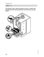
Страница 136: ...136 Checking the boiler water temperature sensors cylinder tem perature sensor or flow temperature sensor for the low loss header 5 X3 d A Troubleshooting Repair cont 5623 520 GB ...

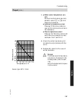
Страница 137: ...unit and check the resistance across terminals X3 4 and X3 5 10 1 10 30 50 70 90 110 Temperature in C 0 4 0 6 0 8 2 4 6 8 20 Resistance in kΩ Sensor type NTC 10 kΩ 2 Check the sensor resistance and compare the actual values with the curve 3 Replace the sensor in the case of severe deviation Danger The boiler water temperature sensors are immersed in the heating water risk of scald ing Drain the bo...

Страница 138: ... both sensors need to be replaced 1 Drain the boiler on the heating water side 2 Pull leads from flow rate sensor A 3 Undo screws and remove faulty flow rate sensor A 4 Install new flow rate sensor A and secure with the screws Troubleshooting Repair cont 5623 520 GB ...

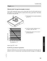
Страница 139: ...ure sensor A 10 1 10 30 50 70 90 110 Temperature in C 0 4 0 6 0 8 2 4 6 8 20 Resistance in kΩ Sensor type NTC 10 kΩ 2 Check the sensor resistance and compare it with the curve 3 Replace the sensor in the case of severe deviation Fault during commissioning fault A3 During commissioning the control unit checks correct placement of the flue gas tem perature sensor If commissioning is terminated and f...

Страница 140: ...r or replace faulty flue gas temperature sensor 3 Press reset button R and repeat com missioning The check is repeated until it is com pleted successfully Checking the fuse F1 A 1 Switch off the power 2 Release the side closures and pivot the control unit down 3 Remove cover A 4 Check fuse F1 see connection and wiring diagram Troubleshooting Repair cont 5623 520 GB ...

Страница 141: ...opened and closed again Note the rotational direction of the mixer motor during its self test Then set the mixer manually to Open Note The flow temperature sensor must now capture a higher temperature If the tem perature drops either the motor is turn ing in the wrong direction or the mixer set is incorrectly fitted Mixer installation instructions Changing the rotational direction of the mixer mot...

Страница 142: ...Pull plug flow temperature sen sor 2 Check the sensor resistance and compare it with the curve Replace the sensor in the case of severe deviation Checking the Vitotronic 200 H accessories The Vitotronic 200 H is connected to the control unit via the LON To test the con nection carry out a subscriber check at the boiler control unit see page 62 Troubleshooting Repair cont 5623 520 GB ...

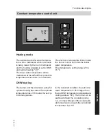
Страница 143: ...boiler water temperature Flow temperature setting range 20 to 74 C DHW heating The burner and the circulation pump for cylinder heating are started if the cylinder temperature lies 2 5 K below the set cyl inder temperature In the delivered condition the set boiler water temperature is 20 K higher than the set DHW temperature adjustable via coding address 60 The burner will be switched off and the ...

Страница 144: ...egu lates the burner accordingly The electronic temperature limiter inside the burner control unit limits the boiler water temperature DHW heating The burner and the circulation pump for cylinder heating are started if the cylinder temperature lies 2 5 K below the set cyl inder temperature In the delivered condition the set boiler water temperature is 20 K higher than the set DHW temperature adjus...

Страница 145: ...ture via coding address 58 in group DHW and activat ing the fourth DHW phase for DHW heat ing Heating is boosted during the periods selected in this time phase Internal extensions accessories Internal extension H1 Function description Weather compensated control unit cont 5623 520 GB Service ...

Страница 146: ...53 in group General Central fault message code 53 0 DHW circulation pump code 53 1 only for weather compensated oper ation Heating circuit pump for heating circuit without mixer code 53 2 Circulation pump for cylinder heating code 53 3 An external safety valve can be connec ted to connection gD Internal extension H2 Function description Internal extensions accessories cont 5623 520 GB ...

Страница 147: ... in group General Central fault message code 53 0 DHW circulation pump code 53 1 only for weather compensated oper ation Heating circuit pump for heating circuit without mixer code 53 2 Circulation pump for cylinder heating code 53 3 An extractor fan can be switched off via connection aBJ when the burner starts Function description Internal extensions accessories cont 5623 520 GB Service ...

Страница 148: ...148 Extension AM1 A1 Circulation pump A2 Circulation pump fÖ Power supply fÖ A Power supply for additional accessories aVG KM BUS Function description External extensions accessories 5623 520 GB ...

Страница 149: ...eating DHW circulation pump Select the output functions by means of the codes on the boiler control unit Function assignment Function Code General group Output A1 Output A2 DHW circulation pump sK 33 0 34 0 delivered cond Heating circuit pump sÖ 33 1 delivered cond 34 1 Circulation pump for cylinder heating sA 33 2 34 2 Function description External extensions accessories cont 5623 520 GB Service ...

Страница 150: ...al input 2 DE3 Digital input 3 0 10 V 0 10 V input fÖ Power supply fÖ A Power supply for additional accessories aBJ Central fault message feed pump DHW circulation pump potential free aVG KM BUS Function description External extensions accessories cont 5623 520 GB ...

Страница 151: ...de d8 3 The effect of the heating program changeover is selected via coding address d5 in the Heating circuit group The duration of the changeover is set via coding address F2 in the Heating cir cuit group Effect of the external blocking func tion on the pumps The effect on the internal circulation pump is selected in coding address 3E in the General group The effect on the respective heating cir ...

Страница 152: ...roup at the boiler control unit Control functions External heating program changeover The External heating program change over function is connected via extension EA1 There are 3 inputs available at extension EA1 DE1 to DE3 The function is selected via the following coding addresses in the General group Heating program changeover Code Input DE1 3A 1 Input DE2 3b 1 Input DE3 3C 1 Select the heating...

Страница 153: ...ng program changeover F2 0 Duration of the operating program changeover 1 to 12 hours F2 1 to F2 12 The operating program changeover stays enabled for as long as the contact remains closed but at least as long as the duration selected in coding address F2 External blocking The External blocking and External blocking and fault message input func tions are connected via extension EA1 There are 3 inp...

Страница 154: ...2 Input DE3 3C 2 The effect on the internal circulation pump is selected in coding address 3F in the General group The effect on the respective heating cir cuit pump is selected in coding address d7 in the Heating circuit group The minimum set boiler water tempera ture in case of external demand is selec ted in coding address 9b in the Gen eral group Venting program During the venting program the ...

Страница 155: ...mperature achieved Operating conditions and outside tem perature during handover The various temperature profiles can be set via coding address F1 in the Heat ing circuit group The function continues after power fail ure or after the control unit has been switched off Heating and DHW is star ted when screed drying is finished or if code F1 0 is set manually Temperature profile 1 EN 1264 4 code F1 ...

Страница 156: ...0 30 20 10 1 5 10 15 20 25 30 Temperature profile 4 Code F1 4 Flow temperature C Days 50 40 30 20 10 1 5 10 15 20 25 30 Temperature profile 5 Code F1 5 Flow temperature C 1 5 10 15 20 25 30 Days 50 40 30 20 10 Function description Control functions cont 5623 520 GB ...

Страница 157: ...ced room temperature the reduced set room tem perature can be automatically raised subject to the outside temperature The temperature is raised in accordance with the selected heating curve but no higher than the set standard room tempera ture The outside temperature limits for the start and end of temperature raising can be set in coding addresses F8 and F9 in the Heating circuit group Function d...

Страница 158: ...re Reducing the heat up time During the transition from operation with reduced room temperature to operation with standard room temperature the boiler water or flow temperature will be raised in accordance with the selected heating curve The boiler water or flow temperature can be automatically increased The value and duration of the additional increase in the set boiler water or flow temperature ...

Страница 159: ...h standard room temperature B Set boiler water or flow temperature in accordance with the selected heating curve C Set boiler water or flow temperature in accordance with coding address FA 50 C 20 60 C D Duration of operation with raised set boiler water or flow temperature in accordance with coding address Fb 60 min Function description Control functions cont 5623 520 GB Service ...

Страница 160: ...ected to the control unit If the assignment of a heating circuit is later cancelled reset coding address A0 in the Heating circuit group for this heating circuit to 0 fault message bC bd bE Electronic combustion control unit The electronic combustion controller uti lises the physical correlation between the level of the ionisation current and the air ratio λ The maximum ionisation cur rent is achi...

Страница 161: ...10 9 1 27 4 9 9 0 8 9 10 6 1 30 5 3 8 7 8 6 10 3 1 34 5 7 8 5 8 4 10 0 1 37 6 1 8 3 8 2 9 8 1 40 6 5 8 1 8 0 9 6 1 44 6 9 7 8 7 7 9 3 1 48 7 3 7 6 7 5 9 0 To achieve an optimum combustion con trol the system regularly carries out an automatic self calibration also after a power failure shutdown For this the combustion is briefly regulated to max ionisation current corresponding to air ratio λ 1 Au...

Страница 162: ...water temperature sen sor aA Ionisation electrode aG Flue gas temperature sensor gF Ignition unit a Ö Fan motor a Ö A Fan motor control a Ö Modulation coil A Flow rate sensor Designs Connection and wiring diagram internal connections 5623 520 GB ...

Страница 163: ...163 A1 Main PCB A2 Power supply unit A3 Optolink A4 Burner control unit A5 Programming unit A6 Coding card Designs Connection and wiring diagram external connections 5623 520 GB Service ...

Страница 164: ...low temperature sensor low loss header Cylinder temperature sensor plug on the cable harness sÖ Heating circuit pump or boiler cir cuit pump sA Circulation pump for cylinder heat ing sK DHW circulation pump dG Gas solenoid valve fÖ Power supply lH Power supply for accessories and Vitotrol 100 a Ö Fan motor aYA Gas pressure switch aVG KM BUS Designs Connection and wiring diagram external cont 5623 ...

Страница 165: ...ed Serial no see type plate A Assembly from this parts list Position number of the individual part within the assembly from this parts list Standard parts are available from your local supplier Parts lists Ordering parts 5623 520 GB Service ...

Страница 166: ...166 D B C E F A A Type plate B Casing assembly C Heat cell assembly with burner D Control unit assembly Parts lists Overview of the assemblies 5623 520 GB ...

Страница 167: ... clip 2 pce 0002 Viessmann logo 0003 Safety guard 0004 Control unit support 0005 Siphon grommet 0006 Wall mounting bracket 0007 Cover panel 0008 Front panel 0001 0002 0004 0006 0001 0002 0008 0003 0005 0007 Parts lists Overview of the assemblies cont 5623 520 GB Service ...

Страница 168: ...tion 0009 Gas supply pipe 0010 Connection pipe 0011 Gasket G1 5 pce 0012 Condensate drain set 0013 Gasket G1 and G1 0014 Heat exchanger with hydraulics 0015 Thermal insulation block 0016 Burner 0006 0014 0015 0013 0012 0011 0008 0007 0006 0005 0004 0003 0002 0001 0013 0011 0002 0003 0015 0005 0013 0011 0009 0010 0016 0012 0007 0004 0008 0001 0002 0003 Parts lists Heat cell assembly 5623 520 GB ...

Страница 169: ... 0010 Cylinder burner gauze assembly 0011 Adapter flange 0012 Ignition unit 0013 Ignition electrode block 0014 Burner gauze assembly gasket 0015 Door screws set 0001 0006 0015 0012 0008 0005 0007 0010 0014 0002 0015 0015 0015 0014 0014 0001 0002 0009 0013 0003 0004 0011 0015 0015 Hydraulic assembly 0001 Clip Ø 8 5 pce 0002 Temperature sensor 2 pce 0003 Pressure gauge 0004 Flow sensor Parts lists B...

Страница 170: ...g unit for weather compensated mode 0007 Programming unit for constant temperature mode 0008 LON module 0009 Adaptor PCB 0010 Cable harness X8 X9 ionisation 0011 Cable harness 100 35 54 earth 0013 Mating plug 0014 Cable fixing 0015 Locking bolts left and right 0017 Outside temperature sensor RF 0018 Outside temperature sensor NTC 0020 Internal extension H1 Parts lists Hydraulic assembly cont 5623 ...

Страница 171: ...0009 0002 Miscellaneous 0001 Operating instructions for weather compensated mode 0002 Operating instructions for con stant temperature mode 0003 Installation and service instruc tions 0004 Spray paint Vitowhite 0005 Touch up paint stick Vitowhite Parts lists Control unit assembly cont 5623 520 GB Service ...

Страница 172: ...172 0002 0001 0003 0005 0004 Parts lists Miscellaneous cont 5623 520 GB ...

Страница 173: ... Carbon dioxide content CO2 for natural gas At lower heating output by vol 7 5 9 6 At upper heating output by vol 7 5 9 6 For LPG At lower heating output by vol 9 0 11 3 At upper heating output by vol 9 0 11 3 Oxygen content O2 At lower heating output by vol 3 8 7 3 At upper heating output by vol 3 8 7 3 Carbon monoxide content CO At lower heating output ppm 1000 At upper heating output ppm 1000 C...

Страница 174: ...kW 32 125 32 150 Rated heat input range kW 30 118 30 142 Power consumption in the delivered condition W 146 222 Connection values relative to the max load With Natural gas E m3 h 12 49 15 03 Natural gas LL m3 h 14 51 17 47 LPG kg h 9 23 11 10 Product ID _ 0085CN0050 Note The connection values are only for documentation purposes e g in the gas contract application or to estimate a supplementary vol...

Страница 175: ...EC 2006 95 EC 2004 108 EC 2009 142 EC This product meets the requirements of the Efficiency Directive 92 42 EEC for con densing boilers Allendorf 01 June 2012 Viessmann Werke GmbH Co KG Authorised signatory Manfred Sommer Manufacturer s certificate according to the 1st BImSchV Ger many We Viessmann Werke GmbH Co KG D 35107 Allendorf confirm that the product Vitodens 200 W complies with the NOx lim...

Страница 176: ...tension kit for heating circuit with mixer 141 External blocking 153 External demand 154 F Fault codes 119 Fault history 117 Fault manager 61 Fault memory 117 118 Faults 117 Filling the system 31 Fill water 31 Flue gas temperature sensor 139 Function descriptions 143 Function testing 114 Fuse 140 G Gas supply pressure 40 Gas train 40 Gas type 36 Gas type conversion 37 H Heat exchanger cleaning 47 ...

Страница 177: ...irection of mixer motor Changing 141 Checking 141 S Screed drying 154 Screed drying function 154 Service level calling up 107 Service menu calling up 107 Set room temperature selection 59 Siphon 35 48 Specification 174 Standard set room temperature 59 Static pressure 40 Supply pressure 39 System pressure 31 System schemes 51 66 T Tightness test balanced flue system 42 Time setting 33 V Venting 34 ...

Страница 178: ...178 5623 520 GB ...

Страница 179: ...179 5623 520 GB ...

Страница 180: ... plate 7506550 7506551 Viessmann Limited Hortonwood 30 Telford Shropshire TF1 7YP GB Telephone 44 1952 675000 Fax 44 1952 675040 E mail info uk viessmann com Viessmann Werke GmbH Co KG D 35107 Allendorf Telephone 49 6452 70 0 Fax 49 6452 70 2780 www viessmann com 5623 520 GB Subject to technical modifications ...

Отзывы: