background image

Setting the White Balance

Use this procedure to set color tone produced by the plasma dis-
play. 
Example: Setting “6500K” 

Press  the  MENU  button  on  the  remote  control  to  display  the 
MAIN MENU on the screen, then... 

1.  Use  the    and    buttons  to  select  “PICTURE  ADJUST”, 
then press the MENU button. The “PICTURE ADJUST” screen 
appears. 

2. Use the   and   buttons to select “WHITE BAL”. 

3. Use the   and   buttons to select “6500K”. 
The  mode  switches  as  follows  when  the    and    buttons  are 
pressed: 


5400K


6500K


8500K


9300K

* See below to set “WHITE BALANCE ADJUST”.

*  If  neither  the    or    button  is  pressed  within  5  seconds,  the 
current selection is set and the previous screen reappears.
4. 

Once the setting is completed...

Press the EXIT button to return to the main menu. To delete the 
main menu, press the EXIT button once more.

Adjusting the color to the desired level

Use  this  procedure  to  adjust  the  white  balance  for  each  color 
temperature to achieve the desired color quality. 
Example: Adjusting the “GAIN RED” of “9300K” color 
temperature.

Perform the following operations.
Press  the  MENU  button  on  the  remote  control  to  display  the 
MAIN MENU on the screen, then... 

Perform Steps 1-3 of WHITE BAL., then...


36

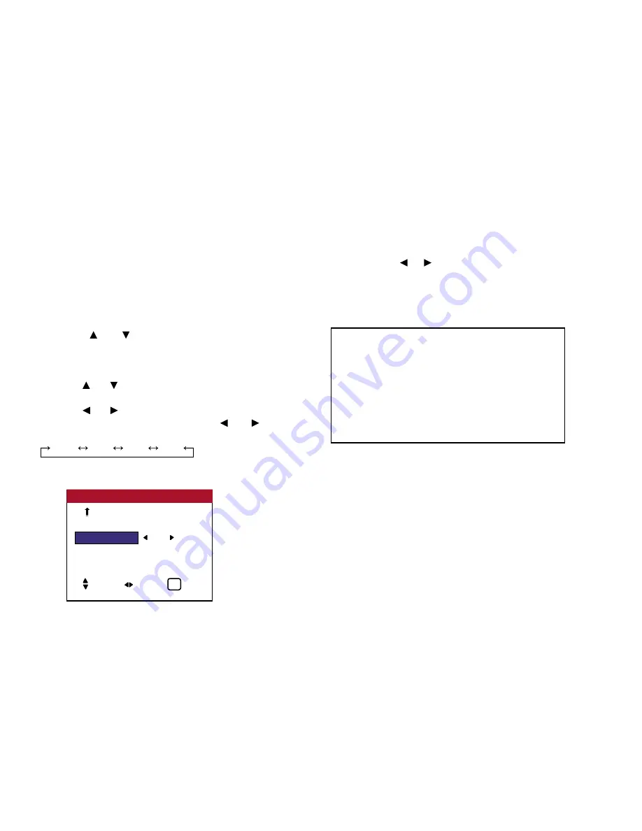
WHITE BAL


:     6500K

GAMMA CURVE

  :     2.2

DITHER  

:     AUTO

COLOR CHART 

PICTURE ADJUST


2 / 2

SEL.              ADJ.                    EXIT

EXIT

PREVIOUS PG.

Information

 Setting the color temperature

5400K .................... Redder

6500K .................... Slightly redder

8500K .................... Standard (slightly bluer)

9300K .................... Bluer

 Restoring the factory default settings

Select “FACTORY” under the SETTING 1 menu. Note that 

this also restores other settings to the factory defaults.

OSD (On Screen Display) Controls

Содержание PlasmaView VP-42

Страница 1: ...VP 42 VP 42HD VP 50 VP 60 Owner s Manual...

Страница 2: ...n Signal of the RGB 3 In Connector DVI Connector 22 Basic Operations 23 Power 23 Volume 23 Mute 23 Display 23 Timer Off 24 Aspect Ratio Controls 25 Aspect Ratio Operations Manual 25 Wide Screen Operat...

Страница 3: ...Vidikron s superior video processing with 3 2 film detection circuitry is built into the monitors and provides exceptional detail and artifact free video enhancement elevating even standard NTSC mate...

Страница 4: ...nts of the package Plasma display monitor Power cord Remote control with two AAA batteries User s manual Safety metal fittings Screws for safety metal fittings Ferrite core small x 2 large x 2 bands C...

Страница 5: ...a commercial environment This equipment generates uses and can radiate radio frequency energy and if not installed and used in accordance with the instruction manual may cause harmful interference to...

Страница 6: ...ower to the monitor and unplug the power cord If the room where the monitor is installed is particularly hot move the monitor to a cooler location and wait for 60 minutes to cool the monitor If the pr...

Страница 7: ...unit and might even cause a fire hazard 2 Handle the unit carefully when installing it and do not drop 3 Set the unit away from heat excessive dust and direct sunlight 4 Protect the inside of the uni...

Страница 8: ...please adhere to the following guidelines and recommendations for minimizing the occurrence of image burn Always enable and use your computer s screen saver function during use with a computer input...

Страница 9: ...ure that images displayed in the 4 3 aspect ratio mode black or gray stripes but no picture information is present on the left and right edges of the screen are used as infrequently as possible This w...

Страница 10: ...sale as evidence of the purchase date IMPORTANT WARRANTY REGISTRATION Please fill out and mail your warranty registration card It is imperative that Vidikron knows how to reach you promptly if we sho...

Страница 11: ...f the nearest VIDIKRON authorized service location or for additional information about this Limited Warranty please call or write VIDIKRON Attn Customer Service Department 2900 Faber Street Union City...

Страница 12: ...d on its own Be sure to use a stand or original mounting unit wallmount unit stand etc For correct installation and mounting it is required to use a trained Vidikron Authorized Dealer Failure to follo...

Страница 13: ...EO2 VIDEO3 HD COMP DTV RGB PC3 RGB PC2 RGB PC1 COMP VIDEO1 VIDEO2 VIDEO3 HD1 COMP1 DTV1 RGB PC2 RGB PC1 HD2 COMP2 DTV2 5 LEFT and RIGHT Enlarges or reduces the image Functions as the CURSOR buttons in...

Страница 14: ...creen E DVD1 HD1 Connect DVD s High Definition or Laser Disks etc here F RGB2 DVD2 HD2 RGB2 Connect an analog RGB signal and the synchronization signal DVD2 HD2 Connect DVD s High Definition sources L...

Страница 15: ...IN SPEAKERS MUST HAVE MORE THAN 7WATT RATING IMPEDANCE 6 OHM RIGHT LEFT AC IN A B VIDEO IN OUT VIDEO 1 VIDEO 2 VIDEO 3 AUDIO 1 DVD 1 HD 1 R MONO L Y Cb Pb Cr Pr RGB 2 DVD 2 HD 2 RGB 1 R VD G B HD I N...

Страница 16: ...he main menu to go to the sub menu 5 VID 1 2 3 Press this button to select VIDEO as the source VID1 VID2 VID3 VIDEO can also be selected using the INPUT SELECT button on the monitor 6 COMP 1 2 Press t...

Страница 17: ...DISPLAY Displays the source settings on the screen 13 LIGHT Press this to illuminate the buttons Not available on all models Remote Control continued Part Names and Functions 1 2 4 6 9 7 10 13 8 5 12...

Страница 18: ...placement Insert the 2 AAA batteries making sure to set them in with the proper polarity 1 Press and open the cover 2 Align the batteries according to the and indication inside the case 3 Replace the...

Страница 19: ...ther or use different types together Do not take apart the batteries heat them or throw them into a fire Operating Range Use the remote control within a distance of about 23 ft 7m from the front of th...

Страница 20: ...R MONO L AUDIO 3 R MONO L Cr Pr Y Cb Pb RGB 3 External Control IN OUT REMOTE VCR or Laser Disc Player VIDEO 1 3 DVD Player IBM VGA or Compatibles To Mini D Sub 15 pin connector on the plasma monitor T...

Страница 21: ...lation instructions 3 This plasma monitor provides signal compatibility up to VESA 1600 x 1200 UXGA However it is not recommended to use this resolution due to image readability on the monitor s nativ...

Страница 22: ...your VCR or laser disc player has this capability Be careful to keep your right and left channel connections correct for stereo sound 3 Turn on the plasma monitor and the VCR or laser disc player Note...

Страница 23: ...ground 7 Green ground 8 Blue ground 9 No connection 10 Sync signal ground 11 No connection 12 Bi directional DATA SDA 13 Horizontal sync or Composite sync 14 Vertical sync 15 Data clock Pin No Signal...

Страница 24: ...d and the standby mode is set only when turning off the unit with the remote control VOLUME To adjust the sound volume 1 Press and hold the VOLUME button on the remote control or the unit to increase...

Страница 25: ...AUTO OFF button once 2 The remaining time is displayed then turns off after a few seconds 3 When five minutes remain the remaining time appears until it reaches zero To cancel the off timer 1 Press t...

Страница 26: ...LTR BOX STD 4 3 ANAMPHC INTELLIWIDE LTR BOX mode The image in the Letterbox mode will be zoomed in and the top and bottom portion blanked off This ratio is best suited for LaserDisc movies or non anam...

Страница 27: ...s reaching the most extreme stretch at the far edges of the picture non linear scaling In addition we apply a very slight vertical stretch uniformly no graduation which results in a very small amount...

Страница 28: ...ion LTR BOX mode When wide signals are input NOTE Do not leave the displayed in 4 3 mode for an extended period This can cause a phosphor burn in Information Supported resolution See page 106 for deta...

Страница 29: ...ected item by using the cursor buttons on the remote control 5 Change the adjustments or the settings that are stored in memory The change is stored until you change it again 6 Repeat steps 2 5 to adj...

Страница 30: ...justs the blue content signal level Center Yes RED OFFSET Adjusts the red content black level Center Yes GREEN OFFSET Adjusts the green content black level Center Yes BLUE OFFSET Adjusts the blue cont...

Страница 31: ...Min Yes COMPUTER Turn this on to have the monitor automatically adjust FINE PICTURE and PICTURE ADJ OFF No FINE PICTURE Adjusts for flickering on the computer image Min 2 Yes PICTURE ADJUST Adjusts fo...

Страница 32: ...picture intermittently OFF Yes INVERSE Displays a negative positive inverse image or an all white screen OFF Yes IMAGE SWEEP Sweeps the screen with a white vertical bar OFF Yes SOFTEN Softens the det...

Страница 33: ...ch display turns on after a delay time OFF Yes LUM SET LINK Sets a uniform brightness for each display OFF Yes REPTR TIMER Sets two programmable timers OFF Yes Main Menu Sub Menu Functions Default Res...

Страница 34: ...eturn to the main menu To delete the main menu press the EXIT button once more NOTE If CAN NOT ADJUST appears When trying to enter the PICTURE submenu make sure IMAGE MEM is not set to FACTORY 33 CONT...

Страница 35: ...within 5 seconds the current selection is set and the previous screen reappears 4 Once the adjustment is completed Press the EXIT button to return to the main menu To delete the main menu press the E...

Страница 36: ...n the and buttons are pressed OFF VID NR 1 VID NR 2 VID NR 3 If neither the or button is pressed within 5 seconds the current selection is set and the previous screen reappears 4 Once the setting is c...

Страница 37: ...the EXIT button to return to the main menu To delete the main menu press the EXIT button once more Adjusting the color to the desired level Use this procedure to adjust the white balance for each colo...

Страница 38: ...to display the MAIN MENU on the screen then 1 Use the and buttons to select PICTURE ADJUST then press the MENU button The PICTURE ADJUST screen appears 2 Use the and buttons to select GAMMA CURVE 3 Us...

Страница 39: ...ons to select AUTO The mode switches as follows each time the or button is pressed AUTO STILL MOTION DIFFUSED 4 Once the setting is completed Press the EXIT button to return to the main menu To delete...

Страница 40: ...ns If neither the or button is pressed within 5 seconds the current selection is set and the previous screen reappears To continue making other adjustments Repeat from step 3 5 Once the setting is com...

Страница 41: ...RGB 1 AUDIO SETUP SEL ADJ EXIT EXIT Information Audio setup menu BASS Controls the level of low frequency sound TREBLE Controls the level of high frequency sound BALANCE Controls the balance of the le...

Страница 42: ...AUDIO INPUT1 3 To set the AUDIO INPUT1 to VIDEO2 Use the and buttons to select VIDEO2 The mode switches as follows each time the and buttons is pressed The available sources depend on the setting of...

Страница 43: ...e The mode switches as follows when the and buttons are pressed STD 4 3 ANAMPHC I WIDE LTR BOX The mode can also be switched by pressing the ASPECT button on the remote control 2 To adjust the vertica...

Страница 44: ...H SHIFT Adjusts the horizontal position of the image V SIZE Adjusts the vertical size of the image Except for I WIDE mode H SIZE Adjusts the horizontal size of the image Except for I WIDE mode FINE PI...

Страница 45: ...setting is completed Press the EXIT button to return to the SETTING 1 menu To return to the main menu press the EXIT button once more 44 OSD On Screen Display Controls Information DISPLAY OSD setting...

Страница 46: ...to return to the main menu To delete the main menu press the EXIT button once more OSD ORBITER settings ON The position of the menu will be shifted by eight dots each time OSD is displayed OFF OSD wi...

Страница 47: ...tches as follows each time the or button is pressed AUTO STILL MOTION RESIZE1 RESIZE2 DTV 4 Once the setting is completed Press the EXIT button to return to the main menu To delete the main menu press...

Страница 48: ...menu To delete the main menu press the EXIT button once more MOTION The video signal from a scan converter will be converted to RGB signals to make the picture more easily viewable Use this mode for a...

Страница 49: ...ed Press the EXIT button to return to the main menu To delete the main menu press the EXIT button once more 48 OSD On Screen Display Controls OSD BNC INPUT COMP D SUB TYPE RGB RGB TYPE AUTO HD TYPE 10...

Страница 50: ...buttons to select ON then press the MENU button When the SETTING NOW screen disappears then all the settings are restored to the default values 4 Once the setting is completed Press the EXIT button to...

Страница 51: ...on The auto off function automatically reduces the monitor s power consumption if the computer s keyboard or mouse is not operated for a certain amount of time This function can be used when using the...

Страница 52: ...tions Press the MENU button on the remote control to display the MAIN MENU on the screen then 1 Use the and buttons to select SETTING 2 then press the MENU button The SETTING 2 menu appears 2 Use the...

Страница 53: ...SETTING See page 53 to set ORBITER See page 54 to set INVERSE See page 56 to set IMAGE SWEEP 4 Once the setting is completed Press the EXIT button to return to the SETTING 2 screen To return to the ma...

Страница 54: ...Sets maximum brightness The brightness level decreases in the order of SET 1 2 3 SET 3 provides minimum brightness Information ORBITER settings OFF Orbiter mode does not function AUTO1 The picture mo...

Страница 55: ...1 LINE 2 LINE 19 LINE 20 LINE TIME 1 M 2 M 3 M 4 M 5 M INVERSE Use this to set the inverse mode or to display a white screen Example Setting INVERSE to WHITE Perform Steps 1 2 of PIXL PROTECT then 3...

Страница 56: ...ng is completed Press the EXIT button to return to the PIXL PROTECT screen Information Setting the time ACTIVE Set the time duration for INVERSE WHITE When the ACTIVE is set to ON the mode will stay o...

Страница 57: ...arts in 30 minutes and proceeds for one hour and a half Perform Steps 1 3 of IMAGE SWEEP then 4 Use the and buttons to select ON then press the MENU button The IMAGE SWEEP screen appears 5 Adjust the...

Страница 58: ...hen press the MENU button The SETTING 2 menu appears 57 OSD On Screen Display Controls Information Setting the time ACTIVE Set the time duration for IMAGE SWEEP When the ACTIVE is set to ON the mode w...

Страница 59: ...S2 3 Use the and buttons to select AUTO The mode switches as follows each time the and buttons is pressed OFF AUTO Information SIDEBAR LEV settings This adjusts the brightness of the black the Sidebar...

Страница 60: ...ressed PLUG PLAY PC STB DVD BLACK LEVEL LOW HIGH OSD On Screen Display Controls 59 Information S1 S2 Settings AUTO Adjusts the screen size automatically according to the S1 S2 video signal OFF Turns t...

Страница 61: ...ME This sets the day of the week and present time Example Setting WEDNESDAY 22 05 Perform Steps 1 2 of TIMER then 3 Use the and buttons to select PRESET TIME then press the MENU button The PRESET TIME...

Страница 62: ...IMER menu PRESENT TIME SEL ADJ EXIT EXIT RETURN DAYLIGHT SAVING TIME OFF WEDNESDAY 22 05 00 PRESENT TIME RETURN DAYLIGHT SAVING TIME OFF WEDNESDAY 22 05 00 SET SEL OK EXIT MENU ENTER EXIT Information...

Страница 63: ...en appears 5 Adjust using the and buttons and ZOOM button The mode switches as follows each time the ZOOM button is pressed DATE SUN MON SAT SUN MON SAT ON OFF Hour 00 01 02 21 22 23 MINUTE 00 01 02 5...

Страница 64: ...which the power will be turned off in the 24 hour format INPUT Set the input mode that will be displayed when the timer is on FUNCTION Set the PIXL PROTECT function To reset the program Align the curs...

Страница 65: ...tton on the remote control to display the MAIN MENU on the screen then 1 Use the and buttons to select SETTING 3 then press the MENU button The SETTING 3 screen appears 2 Use the and buttons to select...

Страница 66: ...and buttons to select SETTING 3 then press the MENU button The SETTING 3 screen appears 2 Use the and buttons to select IR ENABLE 3 To set the IR ENABLE to OFF Use the and buttons to select OFF then p...

Страница 67: ...isables remote control wireless transmission Set OFF to avoid unwanted control from other remote controls Restoring the factory default settings Select FACTORY under the SETTING 1 menu Note that this...

Страница 68: ...special remote control available only from Vidikron factory Service Department Example Setting 2 1 Use the and buttons to select ID NUMBER 2 To set the ID NUMBER to 2 Use the and buttons to select 2 T...

Страница 69: ...VIDEO WALL using and buttons See page 69 to set DIVIDER See page 69 to set POSITION See page 70 to set DISP MODE See page 70 to set AUTO ID See page 71 to set IMAGE ADJUST See page 72 to set P ON DELA...

Страница 70: ...nd buttons to select NO 4 The mode switches as follows each time the or button is pressed 4 Screens NO 1 NO 2 NO 3 NO 4 9 Screens NO 7 NO 8 NO 14 NO 15 69 OSD On Screen Display Controls Information Re...

Страница 71: ...plays connected to each other Example Setting ON 70 OSD On Screen Display Controls POSITION NO 4 VIDEO WALL POSITION SEL ADJ EXIT EXIT Information VIDEO WALL POSITION settings 1 Screen There is no nee...

Страница 72: ...ps 1 2 of VIDEO WALL then 3 Use the and buttons to select IMAGE ADJUST then press the MENU button The IMAGE ADJUST screen ap pears 71 OSD On Screen Display Controls Information AUTO ID settings ON Ena...

Страница 73: ...Setting ON Perform Steps 1 2 of VIDEO WALL then 3 Use the and buttons to select P ON DELAY 4 Use the and buttons to select ON The mode switches as follows each time the or button is pressed OFF ON Inf...

Страница 74: ...Turns on the main power of all displays at the same time Once this function has been set to ON POWER ON OFF button on the remote control does not function except for the No 1 monitor By pressing the...

Страница 75: ...Sets the individual screen brightness for each screen in a 2x2 video wall Set OFF in a 3x3 video wall When this function is set ON connect your plasma displays with the remote cable optional in the o...

Страница 76: ...01M 00H02M 00H03M 04H14M 04H15M 6 Once the setting is completed Press the EXIT button to return to the VIDEO WALL screen Information REPTR TIME settings If you set both timers Timer 1 and Timer 2 run...

Страница 77: ...screen appears 2 To select DEUTSCH Use the and buttons to select DEUTSCH The mode switches as follows each time the and buttons are pressed ENGLISH DEUTSCH FRAN AIS ITALIANO ESPA OL 3 Once the setting...

Страница 78: ...AIN MENU on the screen then 1 Use the and buttons to select VIDEO STANDARD then press the MENU button The VIDEO STANDARD screen appears 2 To select 3 58NTSC Use the and buttons to select 3 58NTSC The...

Страница 79: ...deo standard formats Different countries use different formats for video signals Set to the video standard used in your current country AUTO The video standards are automatically identified and the fo...

Страница 80: ...uipment side Serial port RS 232C connector See the specifications of the equipment that is to be connected for the type of connector and the pin assignment 3 Wiring Use a crossed reverse cable Wire th...

Страница 81: ...nt sending the signal 2 Unit ID 2 Indicates the equipment receiving the signal Command 2 Command 2 along with command 1 is a number used to distinguish each command Check Sum CKS Error Processing and...

Страница 82: ...T RATIO Select DFH 51H 01H 22 V SHIFT Gain Data DFH 7FH 03H 23 H SHIFT Gain Data DFH 7FH 03H 24 V SIZE Gain Data DFH 7FH 03H 25 H SIZE Gain Data DFH 7FH 03H 26 PHASE Gain Data DFH 7FH 03H 27 CLOCK Gai...

Страница 83: ...ansmission Data 9FH 80H 60H 4FH 00H CKS ACK The plasma monitor returns the following ACK when the power is switched on 3FH 60H 80H 4FH 00H CKS NOTE Do not set the Power ON or Power OFF command continu...

Страница 84: ...the plasma monitor Transmission Data 9FH 80H 60H 3EH 00H CKS ACK 3FH 60H 80H 3EH 00H CKS 06 AUDIO MUTE OFF Function The external control equipment switches off AUDIO Mute of the plasma monitor Transmi...

Страница 85: ...DATA00 USER PICTURE Gain Flag 01H DATA01 BRIGHT Gain Flag 08H 09 SHARPNESS GAIN DATA Function The external control equipment changes the SHARPNESS gain data of the plasma monitor Transmission Data DFH...

Страница 86: ...ing video FFH 01 00H 0 01H 01 20H 32 ACK 7FH 60H 80H 7FH 02H DATA00 DATA01 CKS DATA00 USER PICTURE Gain Flag 01H DATA01 COLOR Gain Flag 04H 11 TINT GAIN DATA Function The external control equipment ch...

Страница 87: ...2H LW BLK1 03H NORMAL 04H FACTORY 13 WHITE BAL SELECT Function The external control equipment changes the WHITE BAL of the plasma monitor Transmission Data DFH 80H 60H 00H 01H DATA00 CKS DATA00 00H 54...

Страница 88: ...H 7FH 02H DATA00 DATA01 CKS DATA00 USER PICTURE Gain Flag 01H DATA01 RED Gain Flag 01H 15 GREEN GAIN DATA Function The external control equipment changes the GREEN gain data of the plasma monitor Tran...

Страница 89: ...BLUE Gain 2 Drive D8H 40 FFH 1 00H 0 IEH 30 ACK 7FH 60H 80H 7FH 02H DATA00 DATA01 CKS DATA00 USER PICTURE Gain Flag 01H DATA01 BLUE Gain Flag 03H 17 VID NR MODE SET Function The external control equip...

Страница 90: ...H 7FH 02H DATA00 DATA01 CKS DATA00 USER PICTURE Gain Flag 05H DATA01 BASS Gain Flag 03H 19 TREBLE GAIN DATA Function The external control equipment changes the TREBLE gain data of the plasma monitor T...

Страница 91: ...n EAH 22 FFH 01 00H 0 01H 01 16H 22 ACK 7FH 60H 80H 7FH 02H DATA00 DATA01 CKS DATA00 USER PICTURE Gain Flag 05H DATA01 BALANCE Gain Flag 02H 21 ASPECT RATIO SELECT Function The external control equipm...

Страница 92: ...0H 7FH 02H DATA00 DATA01 CKS DATA00 USER PICTURE Gain Flag 03H DATA01 V SHIFT Gain Flag 01H 23 H SHIFT GAIN DATA Function The external control equipment changes the H SHIFT gain data of the plasma mon...

Страница 93: ...80H 7FH 02H DATA00 DATA01 CKS DATA00 USER PICTURE Gain Flag 03H DATA01 V SIZE Gain Flag 07H 25 H SIZE GAIN DATA Function The external control equipment changes the H SIZE gain data of the plasma moni...

Страница 94: ...H 02H DATA00 DATA01 CKS DATA00 USER PICTURE Gain Flag 03H DATA01 PHASE Gain Flag 03H 27 CLOCK GAIN DATA Function The external control equipment changes the CLOCK gain data of the plasma monitor Transm...

Страница 95: ...as described in the table below Operation On Screen Display OSD Display of items and adjustments on the menu Volume display input display and screen display When screen display is ON When screen disp...

Страница 96: ...F 31 SIDEBAR LEV SET Function The external control equipment sets the SIDEBAR LEV of the plasma monitor Transmission Data DFH 80H 60H C6H 01H DATA00 CKS DATA00 SIDEBAR LEV 00H 0 0FH 15 ACK 7FH 60H 80H...

Страница 97: ...01 01H 1 02H 2 03H 3 34 PIXL PROTECT SET Function The external control equipment sets the LUM SETTING ORBITER and INVERSE inverse of image brightness of the plasma monitor Transmission Data DFH 80H 60...

Страница 98: ...H C7H 00H CKS Note The ACTIVE and the STANDBY can be set in units of 3 minutes Example 03H 9 minutes 1EH 1 hour and 30 minutes 36 IMAGE SWEEP SET Function The external control equipment sets the IMAGE...

Страница 99: ...DATA00 DATA01 CKS DATA00 AUDIO 01H AUDIO 1 02H AUDIO 2 03H AUDIO 3 DATA01 VISUAL INPUT 01H Video 1 02H Video 2 03H Video 3 05H HD HD1 or DVD or DVD1 06H HD2 DTV2 07H RGB 1 PC1 08H RGB 2 PC2 0CH RGB 3...

Страница 100: ...the following ACK when setting the BNC SELECT 7FH 60H 80H 8CH 01H DATA00 CKS DATA00 BNC SELECT 01H RGB 02H Component 03H Video 41 RGB SELECT Function The external control equipment sets the RGB SELEC...

Страница 101: ...080B ACK 7FH 60H 80H 8AH 01H DATA00 CKS DATA00 01H 1035I 02H 1080A 03H 1080B 42 LANGUAGE SELECT Function The external control equipment sets the LANGUAGE SELECT of the plasma monitor Transmission Data...

Страница 102: ...L M 0EH PAL N 44 FREQUENCY REQUEST Function The external control equipment inquires the Horizontal frequency Vertical frequency Horizontal sync polarity Vertical sync polarity Mode and Resolution of t...

Страница 103: ...FH 60H 80H 26H 0BH DATA00 to DATA10 CKS RESOLUTION DATA07 Dots Low order byte 00H 0 No signal 00H FFH 256 DATA08 Dots High order byte 00H 257 No signal 00H FFH DATA09 Lines Low order byte 00H 0 No sig...

Страница 104: ...DATA01 GREEN Gain Offset D8H 40 FFH 1 00H 0 IEH 30 DATA02 BLUE Gain Offset D8H 40 FFH 1 00H 0 IEH 30 ACK continued 7FH 60H 80H 45H 0CH DATA00 to DATA11 CKS DATA03 COLOR Gain E0H 32 COLOR Gain is from...

Страница 105: ...K 47 AUTO SELECT REQUEST Function The external control equipment inquires the current combinations of audio and video inputs for the plasma monitor Transmission Data 1FH 80H 60H 6FH 00H CKS ACK 7FH 60...

Страница 106: ...it 6 1 fixed backup Bit 7 1 fixed backup DATA01 FAILURE MODE 2 1 fixed backup 49 MODEL NAME REQUEST Function The external control equipment inquires the product code of the plasma monitor Transmission...

Страница 107: ...80 1 60 0 31 7 NEG NEG YES YES YES 3 WIDE1 YES 17 800 X 600 56 3 35 2 POS POS YES YES YES YES STILL YES 11 60 3 37 9 POS POS YES YES YES YES STILL YES 12 72 2 48 1 POS POS YES YES YES YES YES 13 75 0...

Страница 108: ...YES YES YES 4 YES NO 40 100 1 108 5 POS POS YES YES YES 4 YES NO 47 1600 X 1200 60 0 75 0 POS POS YES YES YES YES NO 54 65 0 81 3 POS POS YES YES YES YES NO 55 70 0 87 5 POS POS YES YES YES YES NO 56...

Страница 109: ...uite for the input signals is set automatically If the picture is not displayed properly set the RGB mode prepared for the input signals listed in the table above 6 To connect the monitor to a Macinto...

Страница 110: ...cle between the remote control and the monitor Point the remote control at the monitor s remote control sensor when pressing buttons or remove the obstacle Is direct sunlight or strong artificial ligh...

Страница 111: ...rtical sync signal is not present when the Auto Off control is on Check the input signal POWER STANDBY indicator is blinking in red The temperature inside the main unit has become too high and has act...

Страница 112: ...Stereo RCA jacks 2 Composite Video 1 BNC 1 RCA 2 Component Video 1 BNC 1 RCA 1 S Video 1 RGB 15 pin mini D Sub 1 RGB via BNC 1 DVI w HDCP 1 RS 232 3 Stereo RCA jacks 2 Composite Video 1 BNC 1 RCA 2 Co...

Страница 113: ...ts and labor from the date of delivery to the end user 1 One year parts and labor from the date of delivery to the end user 1 One year parts and labor from the date of delivery to the end user All spe...

Страница 114: ...113 DIMENSIONS 40 301 1 665 24 220 4 899 1 474 42 diagonal VP 42 VP 42HD...

Страница 115: ...114 Dimensions 2 172 48 407 29 286 1 667 3 941 50 diagonal VP 50...

Страница 116: ...115 Dimensions 2 227 58 117 34 912 4 855 1 903 60 diagonal VP 60...

Страница 117: ...RUMA 010550 4 04 v2 0 VIDIKRON 2900 Faber Street Union City CA 94587 Ph 510 324 5900 Fax 510 324 5905 1 888 4 VIDIKRON...

Отзывы: