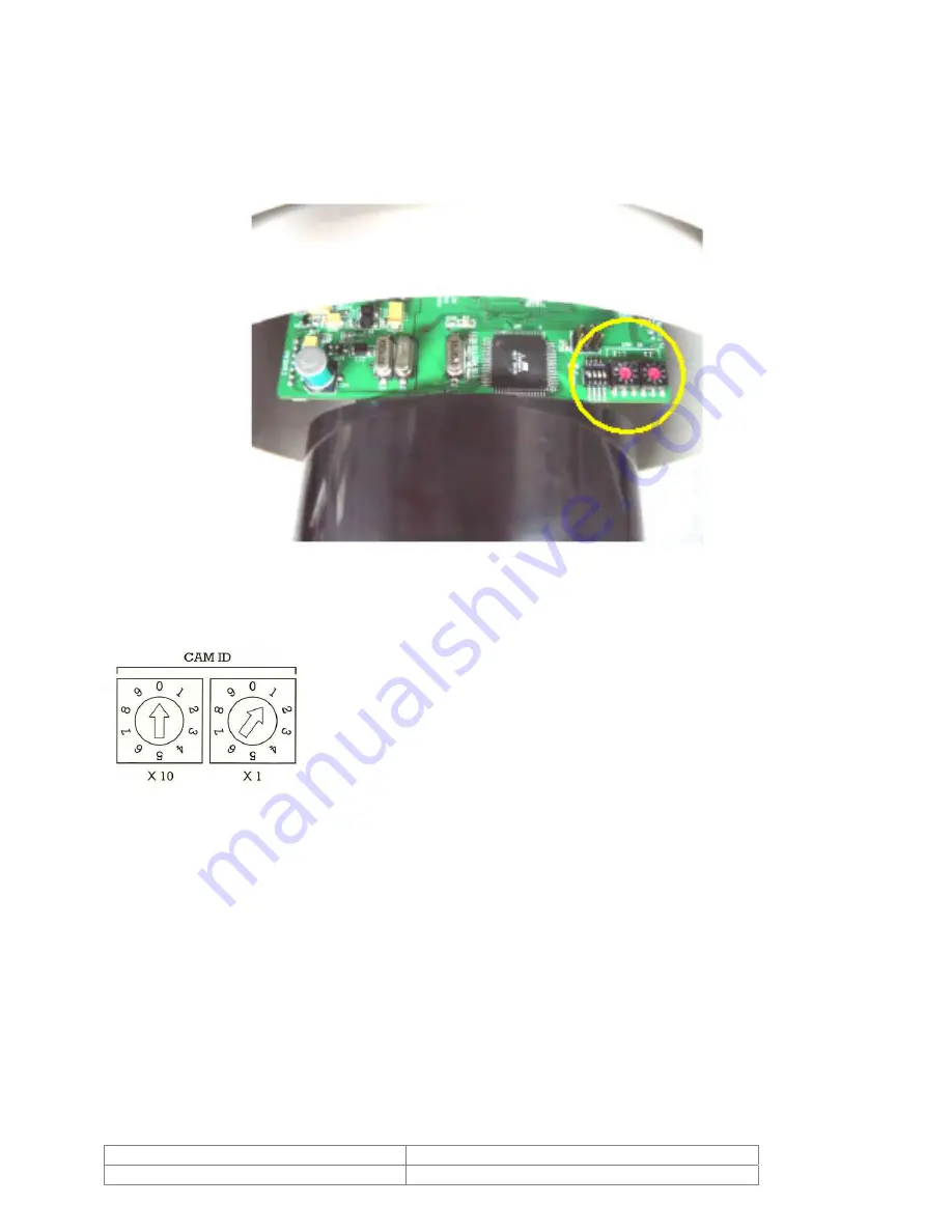
4. Installation
4.1. DIP Switch Setup
Before you install the camera, please set the DIP switches on the PCB to configure the
camera ID, communication protocol and terminal resistor.
4.1.1. Camera ID Setup
×
10 = 10’s digit and x1 = 1’s digit for decimal number. By
turning the arrow with a screwdriver, you can set up the
camera’s ID number.
For example, the left figure shows an example when Camera ID
is 1.
The range of ID is 1~99. Do not use 0 as camera ID. Factory
default of Camera ID is 1.
If you want to control a certain camera through the joystick
controller or DVR, you must match the camera ID with Cam ID
setting of the controller or DVR. Keep a list of the different
camera ID numbers and their locations.
Doc # INS 20/21Z704T-PZ
Issue Date: 03/22/2007
Revision: C
Page
8
of
32


