


If the actual supply voltage is higher than the voltage on the rating label (or the voltage
for which the furnace was last set), immediately after switch-on set the temperature
setpoint to zero, to prevent heating and drawing excessive current.
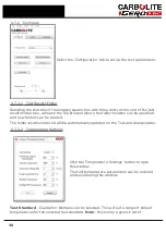
First select user level 2. Press and hold the page
until ‘Access Goto’ is displayed.
Select Level 2 using the down
or up
. Access pass code should now be displayed.
Using the down
or up
enter pass code 9. The word 'Pass' should be shown briefly
and then the display will revert back to main display screen.
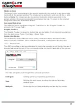
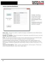
To Select Output high. From the main screen. Press page
twice to display 'Control
output High'. Using the down
or up
keys select the correct power setting.
Correct values for the OP.Hi parameter, with new elements, are:
200 V
208 V
220 V
380 V
230 V
400 V
240 V
415 V
79%
74%
65%
60%
55%
See also the section 5.3
3.7
Exhaust Vent Connections
Note
: Significant amounts of carbon monoxide may be exhausted from
the work tube during the use of this furnace. Carbon monoxide is toxic
and inflammable (see section 1.2) it is recommended that the vent tube
is routed out of the building.
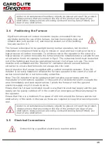
The furnace must always be positioned as recommended in section 3.4.
The furnace has two exhaust vents, the main vent at the back of the heating chamber
and a safety pressure relief vent at the side of the furnace. The purpose of the safety
vent is to prevent dangerous pressure build up as the furnace warms up if the main
vent tube becomes blocked.
The main vent and the safety pressure relief vent must be connected to separate vent
runs and routed out of the building.
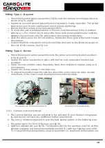
With the back panel removed access is gained to the main vent tube fitting situated on
the work tube back seal assembly below the thermocouples. The main vent tube fitting
is a 12 mm x 3/8" BSP adapter suitable for connecting 12 mm diameter copper tube.
See fig 6.
The safety pressure relief vent tube fitting is a 6 mm x 1/8" BSP adapter suitable for
connecting 6 mm copper tube. See fig 11a.
Note
: It is important that the vents are not restricted in any way, do not use a tube of
less than 6 mm diameter for the safety pressure relief vent connection and 12 mm for
the main vent connection.
Check regularly that the main and safety pressure relief vents are clear from
obstructions.
17
Содержание CARBOLITE GERO CAF G5
Страница 63: ...Fig 3 Front Tube Seal Assembly Fig 4 Door Arm Assembly 63 ...
Страница 64: ...Fig 5a Camera Mounting Bracket Fig 5b Lens and Camera Assembly 64 ...
Страница 65: ...Fig 5c Sliding the Camera Mounting Bracket Assembly onto the Door Arm 65 ...
Страница 66: ...Fig 5d Securing the Camera Mounting Bracket Assembly to the Door Arm 66 ...
Страница 67: ...Fig 5e Mounting the Lens and Camera Assembly 67 ...
Страница 68: ...Fig 5f Lens and Camera Assembly in Position 68 ...
Страница 69: ...Fig 6a Rear View of the Standard CAF G5 Furnace Showing Brick Box Assembly 69 ...
Страница 70: ...Fig 6b Rear View of the CAF G5 Biomass Furnace with Rear Illumination Showing Brick Box Assembly 70 ...
Страница 71: ...Fig 7 Front Tube Seal Position 71 ...
Страница 72: ...Fig 8 Tube End Seal Assembly Tightening Sequence Fig 9 Work Tube Front Support 72 ...
Страница 73: ...Fig 10 Fitting the Door Arm Assembly Fig 10a Adjusting the Door Arm Assembly 73 ...
Страница 74: ...Fig 11a Furnace Case and Controls 74 ...
Страница 75: ...Fig 11b Gas Inlet Pipe Fig 12 Positioning the Furnace 75 ...
Страница 76: ...Fig 13a Positioning Samples on the Sample Carrier Fig 13b Loading Samples into the Mouth of the Work Tube 76 ...
Страница 77: ...Fig 13c Loading Samples into the Work Tube 77 ...
Страница 78: ...Fig 16 File Folder 78 ...
Страница 79: ...Fig 17 Door Arm Assembly Exploded View 79 ...
Страница 82: ...SST DT HT FT Fig 18 Report Sheet Page 2 Side View Plan View Fig 19 Formed Wire Sample 82 ...
Страница 83: ...Fig 20 Sample Carrier Sample Tiles and Sample Positions 83 ...
Страница 84: ...Fig 21a Coal and Coke Test Piece Mould Fig 21b Biomass Test Piece Mould and Hand Press 84 ...
Страница 85: ...Fig 22 Sample Loading Tool Fig 23 Camera Ethernet Connection 85 ...
Страница 86: ...Fig 24 LED Driver Connection 86 ...
Страница 87: ...Notes Service Record Engineer Name Date Record of Work ...


