


4.0
Operating Instructions
4.1
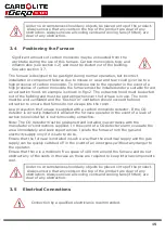
Furnace Start-Up
This furnace is available with either of two gas options (These cannot be converted - see
section 2.0 for more details):
Type 1/
Type 2
CO/
CO
2
Reducing Gas
Rear lighting version available.
Air
Oxidising Gas
N
2
Purge Gas
Compatible with both:
ASTM D1857/ D1857M - 04 (2010) Standard Test Method for Fusibility of
Coal and Coke Ash
&
BS ISO 540: 2008 Hard coal and coke. Determination of Ash Fusibility.
&
DDCEN/ TS 15370-1:2006 Solid biofuels - Method for determination of as
melting behaviour.
&
PD CEN/ TR 15404: 2002 Solid recovered fuels - Methods for the
determination of ash melting behaviour by using characteristic
temperatures.
Type 3
H
2
and
CO
2
Reducing Gas
CO
2
Oxidising Gas
CO
2
Purge Gas
Compatible with - BS ISO 540: 2008
The principle of operation is the same for both types. The furnace is normally supplied
programmed to operate between a pre-determined setpoint (start temperature) and
1500 °C at a ramp rate of 7 °C/ minute. The target temperature is set to 1500 °C to
avoid operating the furnace at high temperatures unnecessarily. See section 4.7.2.2.
The following text describes how to use the furnace with this program.
1. Open the furnace door to check that the silica window is clean. Any slight haze
should be removed before use. If neglected this haze quickly thickens and
becomes impossible to remove. See section 5.5 for instructions on how to remove
and clean the viewing window.
2. Turn on the 'oxidising', 'reducing' and 'purge' gas supplies. If the 'purge' gas is not
present when the furnace electrical supply and instrument switch are on the con-
trol system will activate an alarm buzzer and illuminate a warning light on the
21
Содержание CARBOLITE GERO CAF G5
Страница 63: ...Fig 3 Front Tube Seal Assembly Fig 4 Door Arm Assembly 63 ...
Страница 64: ...Fig 5a Camera Mounting Bracket Fig 5b Lens and Camera Assembly 64 ...
Страница 65: ...Fig 5c Sliding the Camera Mounting Bracket Assembly onto the Door Arm 65 ...
Страница 66: ...Fig 5d Securing the Camera Mounting Bracket Assembly to the Door Arm 66 ...
Страница 67: ...Fig 5e Mounting the Lens and Camera Assembly 67 ...
Страница 68: ...Fig 5f Lens and Camera Assembly in Position 68 ...
Страница 69: ...Fig 6a Rear View of the Standard CAF G5 Furnace Showing Brick Box Assembly 69 ...
Страница 70: ...Fig 6b Rear View of the CAF G5 Biomass Furnace with Rear Illumination Showing Brick Box Assembly 70 ...
Страница 71: ...Fig 7 Front Tube Seal Position 71 ...
Страница 72: ...Fig 8 Tube End Seal Assembly Tightening Sequence Fig 9 Work Tube Front Support 72 ...
Страница 73: ...Fig 10 Fitting the Door Arm Assembly Fig 10a Adjusting the Door Arm Assembly 73 ...
Страница 74: ...Fig 11a Furnace Case and Controls 74 ...
Страница 75: ...Fig 11b Gas Inlet Pipe Fig 12 Positioning the Furnace 75 ...
Страница 76: ...Fig 13a Positioning Samples on the Sample Carrier Fig 13b Loading Samples into the Mouth of the Work Tube 76 ...
Страница 77: ...Fig 13c Loading Samples into the Work Tube 77 ...
Страница 78: ...Fig 16 File Folder 78 ...
Страница 79: ...Fig 17 Door Arm Assembly Exploded View 79 ...
Страница 82: ...SST DT HT FT Fig 18 Report Sheet Page 2 Side View Plan View Fig 19 Formed Wire Sample 82 ...
Страница 83: ...Fig 20 Sample Carrier Sample Tiles and Sample Positions 83 ...
Страница 84: ...Fig 21a Coal and Coke Test Piece Mould Fig 21b Biomass Test Piece Mould and Hand Press 84 ...
Страница 85: ...Fig 22 Sample Loading Tool Fig 23 Camera Ethernet Connection 85 ...
Страница 86: ...Fig 24 LED Driver Connection 86 ...
Страница 87: ...Notes Service Record Engineer Name Date Record of Work ...


