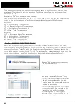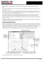
After about one minute slowly slide the samples into the tube at a rate of about 25
mm per minute to make contact with the control thermocouple sheath. See fig 13c.
Once the sample is in position allow a couple of minutes for the cones to burn off
before closing the door, this will allow any vapours given off by the cones to dis-
sipate out of the tube and reduce contamination of the rear end plug and the view-
ing window. See section 5.5.
Note
: It is possible to crack the work tube by inserting samples too quickly. Work
tube failures are not covered by Carbolite Gero's guarantee.
Warning: Do not use the furnace if the work tube is cracked as there is a risk of
exposure to carbon monoxide gas. see section 1.2.
3. Close the furnace door and secure using the two swing bolts. It is important that
the swing bolts are tightened evenly to create a gas tight seal between the door
flanges.
Caution
: To allow the door side shaft to slide in and out, some clearance is
required in the door mechanism; consequently there is a small radial movement in
the door slide arm when the door arm is pushed in towards the work tube. Because
of this radial movement it is possible for the door plug to contact the work tube
from seal assembly if the door handle is lifted as the door arm is pushed inwards:
take care to avoid this happening.
Warning
: Do not operate the furnace with the door or window 'O' ring seals
removed. See fig 17. This will result in high levels of carbon monoxide leaking from
the work tube. see section 1.2.
4. Over-Temperature Alarm
Should a fault develop in the control system which causes the furnace to exceed its
1600 °C limit an over-temperature controller automatically shuts down the furnace
and the over-temperature warning light illuminates on the furnace control panel.
See fig 11a. The over-temperature controller is mounted inside the furnace case
and is not accessible to the operator. Turning the instrument switch off and then on
again once the furnace has cooled down will reset the over-temperature control.
Note
: The over-temperature control is a safety device to protect the furnace in the
event of a fault. If the over-temperature control has operated it is an indication
that there is a fault present in the furnace, it is recommended that the furnace is
not used until the fault has been rectified. Contact our local distributor or our ser-
vice division at the address shown at the back of this manual.
4.6
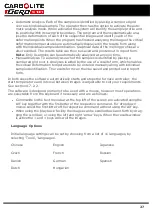
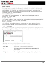
Introduction to the CAF Test Software
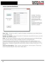
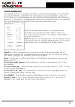
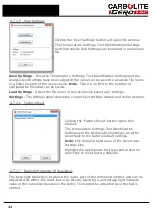
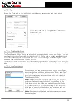
The CAF G5 test software is designed to capture images from the digital camera
mounted on the front of the furnace and store them in sequential order. Whether
automatic analysis, manual analysis or mixture of both is preferred the method of
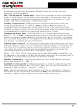
image capture is always the same. Each image captured displays the date, time and the
temperature at which the image was recorded and an optional sample identification.
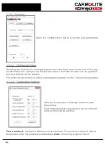
Test images are stored in a folder file name of your choice, which is entered at the start
of the test and each individual image is recorded with the date, time, temperature and
sequence number and can be played back for analysis of the test samples.
Once the images have been captured the analysis of the results can be carried out by
either an automatic or manual method:
26
Содержание CARBOLITE GERO CAF G5
Страница 63: ...Fig 3 Front Tube Seal Assembly Fig 4 Door Arm Assembly 63 ...
Страница 64: ...Fig 5a Camera Mounting Bracket Fig 5b Lens and Camera Assembly 64 ...
Страница 65: ...Fig 5c Sliding the Camera Mounting Bracket Assembly onto the Door Arm 65 ...
Страница 66: ...Fig 5d Securing the Camera Mounting Bracket Assembly to the Door Arm 66 ...
Страница 67: ...Fig 5e Mounting the Lens and Camera Assembly 67 ...
Страница 68: ...Fig 5f Lens and Camera Assembly in Position 68 ...
Страница 69: ...Fig 6a Rear View of the Standard CAF G5 Furnace Showing Brick Box Assembly 69 ...
Страница 70: ...Fig 6b Rear View of the CAF G5 Biomass Furnace with Rear Illumination Showing Brick Box Assembly 70 ...
Страница 71: ...Fig 7 Front Tube Seal Position 71 ...
Страница 72: ...Fig 8 Tube End Seal Assembly Tightening Sequence Fig 9 Work Tube Front Support 72 ...
Страница 73: ...Fig 10 Fitting the Door Arm Assembly Fig 10a Adjusting the Door Arm Assembly 73 ...
Страница 74: ...Fig 11a Furnace Case and Controls 74 ...
Страница 75: ...Fig 11b Gas Inlet Pipe Fig 12 Positioning the Furnace 75 ...
Страница 76: ...Fig 13a Positioning Samples on the Sample Carrier Fig 13b Loading Samples into the Mouth of the Work Tube 76 ...
Страница 77: ...Fig 13c Loading Samples into the Work Tube 77 ...
Страница 78: ...Fig 16 File Folder 78 ...
Страница 79: ...Fig 17 Door Arm Assembly Exploded View 79 ...
Страница 82: ...SST DT HT FT Fig 18 Report Sheet Page 2 Side View Plan View Fig 19 Formed Wire Sample 82 ...
Страница 83: ...Fig 20 Sample Carrier Sample Tiles and Sample Positions 83 ...
Страница 84: ...Fig 21a Coal and Coke Test Piece Mould Fig 21b Biomass Test Piece Mould and Hand Press 84 ...
Страница 85: ...Fig 22 Sample Loading Tool Fig 23 Camera Ethernet Connection 85 ...
Страница 86: ...Fig 24 LED Driver Connection 86 ...
Страница 87: ...Notes Service Record Engineer Name Date Record of Work ...

