


UM001
37
4.3.3
Group Fields
The Group Field parameter consists of a series of one or more 16-bit words per selected output group
which are used to identify the selected output fields for that group. The first series of one or more words
corresponds to the fields for the first selected group, followed by a series of word(s) for the next selected
group, and so on. Each 16-bit word consists of 15 group selection bits (Bit 0 through Bit 14) and an
extension bit (Bit 15). The extension bit in each word is used to indicate the presence of a following
continuation word to select additional (higher-numbered) output fields for the current group. The first
word corresponding to a specific group selects fields 1-15 (with bit offsets 0-14, respectively), the second
word (if present) selects fields 16-30, and so on. Each sequence of field selection words corresponding to
a selected output group ends with a word whose extension bit is not set, and is then followed by a
sequence of words for the next selected group (if any).
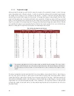
The group fields represent which output types have been selected in the active binary groups. The
number of group fields in the header will depend upon how many groups are active in the message. The
number of group fields present in the header will always be equal to the number of active bits in the group
byte. When parsing the binary packet you can count the number of active bits present in the group byte,
and then you can assume that this number of group fields will be present in the header. For example if
only binary group 1 is selected (Group Byte = 0x01), then only one Group field will be present in the
header, thus the header will be 4 bytes in length. If both binary group 1 and 3 are active (Group Byte =
0x05), then two Group field elements will be present in the header (4 bytes), thus the header in this case
will be 6 bytes in length.
4.3.4
Payload
The payload will consist of the output data selected based upon the bits selected in the group byte and
the group field bytes. All output data in the payload section consist of the active outputs selected for
binary group 1, followed by the active outputs selected for binary group 2, and so forth. No padding bytes
are used between output fields.
4.3.5
CRC
The CRC consists of a 16-bit CRC of the packet. The CRC is calculated over the packet starting just after
the sync byte in the header (not including the sync byte) and ending at the end of the payload. More
information about the CRC algorithm and example code for how to perform the calculation is shown in
the Checksum/CRC section of the Software Architecture chapter. The CRC is selected such that if you
compute the 16-bit CRC starting with the group byte and include the CRC itself, a valid packet will result
in 0x0000 computed by the running CRC calculation over the entire packet. This provides a simple way of
detecting packet corruption by simply checking to see if the CRC calculation of the entire packet (not
including the sync byte) results in zero.
Содержание VN-100
Страница 1: ...UM001 1 Firmware v2 1 0 0 Document Revision 2 22 VN 100 User Manual Embedded Navigation Solutions...
Страница 9: ...UM001 9 2 Specifications 2 1 VN 100 Surface Mount Sensor SMD Electrical Pin assignments top down view...
Страница 14: ...14 UM001 2 3 VN 100 Surface Mount Sensor SMD Dimensions Measurements are in inches 2 4 VN 100 Rugged Dimensions...
Страница 102: ...102 UM001 8 3 Factory Defaults Settings Name Default Factory Value Magnetometer Calibration Control 1 3 5...
Страница 113: ...UM001 113 9 5 Factory Defaults Settings Name Default Factory Value Velocity Compensation Control 1 0 1 0 01...


