


UM001
27
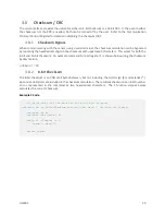
3.6
Communication Protocol
The VN-100 utilizes a simple command based communication protocol for the serial interface. An ASCII
protocol is used for command and register polling, and an optional binary interface is provided for
streaming high speed real-time sensor measurements.
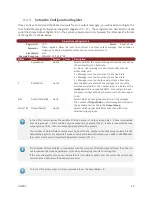
3.6.1
Serial ASCII
On the serial interface a full ASCII protocol provides support for all commands, and register polling. The
ASCII protocol is very similar to the widely used NMEA 0183 protocol supported by most GPS receivers,
and consists of comma delimited parameters printed in human readable text. Below is an example
command request and response on the VN-100 used to poll the attitude (Yaw Pitch Roll Register in the
Attitude subsystem) using the ASCII protocol.
Example Serial Request
$VNRRG,8*4B
Example Serial Response
$VNRRG,08,-114.314,+000.058,-001.773*5F
At the end of this user manual each software subsystem is documented providing a list of all the
commands and registers suported by the subsystem on the VN-100. For each command and register an
example ASCII response is given to demonstrating the ASCII formatting.
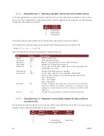
3.6.2
Serial Binary
The serial interface offers support for streaming sensor measurements from the sensor at fixed rates using
user configurable binary output packets. These binary output packets provide a low-overhead means of
streaming high-speed sensor measurements from the device minimizing both the required bandwidth and
the necessary overhead required to parse the incoming measurements for the host system.
3.6.3
Serial Command Prompt
A simple command prompt is also provided on the serial interface, which provides support for advanced
device configuration and diagnostics. The serial command prompt is an optional feature that is designed
to provide more detailed diagnostic view of overall system performance than is possible using normal
command & register structure. It is strictly intended to be used by a human operator, who can type
commands to the device using a simple serial terminal, and is not designed to be used programmatically.
Each software subsystem described in the software module chapters provides information on the
diagnostic commands supported by the serial command prompt at the end of each subsystem section.
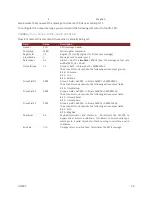
3.7
System Error Codes
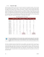
In the event of an error, the VN-100 will output $VNERR, followed by an error code. The possible error
codes are listed in the table below with a description of the error.
Содержание VN-100
Страница 1: ...UM001 1 Firmware v2 1 0 0 Document Revision 2 22 VN 100 User Manual Embedded Navigation Solutions...
Страница 9: ...UM001 9 2 Specifications 2 1 VN 100 Surface Mount Sensor SMD Electrical Pin assignments top down view...
Страница 14: ...14 UM001 2 3 VN 100 Surface Mount Sensor SMD Dimensions Measurements are in inches 2 4 VN 100 Rugged Dimensions...
Страница 102: ...102 UM001 8 3 Factory Defaults Settings Name Default Factory Value Magnetometer Calibration Control 1 3 5...
Страница 113: ...UM001 113 9 5 Factory Defaults Settings Name Default Factory Value Velocity Compensation Control 1 0 1 0 01...


