


36
UM001
4.3
Serial Output Message Format
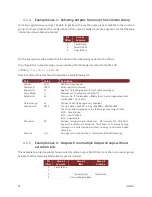
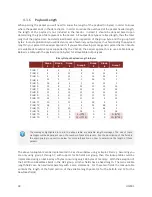
The binary output message packets on the serial interface consist of a simple message header, payload,
and a 16-bit CRC. An example packet is shown below for reference. The header is variable length
depending upon the number of groups active in the message.
Header
Payload
CRC
Field
Sync
Groups
Group Field 1
Group Field 2
Payload
CRC
Byte Offset
0
1
2
3
4
5
6
7
…
N
N+1
N+2
Type
u8
u8
u16
u16
Variable
u16
4.3.1
Sync Byte
The sync byte is the first byte in the header. Its value will always be equal to 0xFA.
4.3.2
Groups
The Group and Group Field parameters consist of variable length arguments to allow conciseness where
possible and expandability where necessary.
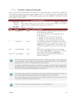
The Group parameter consists of one or more bytes which are used to identify the Binary Output Groups
from which data will be selected for output (see OutputField parameter). Each 8-bit byte consists of seven
group selection bits (Bit 0 through Bit 6) and an extension bit (Bit 7). The extension bit in each byte is used
to indicate the presence of a following continuation byte to select additional (higher-numbered) groups.
The first byte selects Groups 1-7 (with bit offsets 0-6, respectively), the second byte (if present) selects
Groups 8-14, and so on. The sequence of group selection bytes will always end with a byte whose
extension bit is not set. The various groups are shown below.
Name
Bit Offset
Description
Binary Group 1
0
General Purpose Group.
Binary Group 2
1
Time and Event Count Group.
Binary Group 3
2
Inertial Measurement Unit Group.
Binary Group 4
3
Not used. Must be set to zero.
Binary Group 5
4
AHRS Group.
Binary Group 6
5
Not used. Must be set to zero.
Binary Group 7
6
Not used. Must be set to zero.
Binary Group 8
7
Not used. Must be set to zero.
Groups 8-14 are not used, however they are reserved for use in future firmware versions.
Содержание VN-100
Страница 1: ...UM001 1 Firmware v2 1 0 0 Document Revision 2 22 VN 100 User Manual Embedded Navigation Solutions...
Страница 9: ...UM001 9 2 Specifications 2 1 VN 100 Surface Mount Sensor SMD Electrical Pin assignments top down view...
Страница 14: ...14 UM001 2 3 VN 100 Surface Mount Sensor SMD Dimensions Measurements are in inches 2 4 VN 100 Rugged Dimensions...
Страница 102: ...102 UM001 8 3 Factory Defaults Settings Name Default Factory Value Magnetometer Calibration Control 1 3 5...
Страница 113: ...UM001 113 9 5 Factory Defaults Settings Name Default Factory Value Velocity Compensation Control 1 0 1 0 01...


