background image


7. Installing Software 

Green21 (Model: PCT-90LH) Installation Manual 

97 

EN

G

LISH


Finalizing the Parameters Settings 

1.  Click on 

Exit 

 Close 

and


terminate the control panel. 

2.  Make sure to exit the imaging program (main GUI). 

3.  Reset the equipment to apply the changes. 

4.  Setting Up the IP Address for the LCD 

For the LCD to communicate with the PC, the proper IP address should be set on 

the PC. The following screenshots are taken in the Windows 7. 

5.  From the desktop, right-click on the 

Network

 icon and click on 

Properties


Figure 7-39. Network Properties 

6.  Select “Change adapter settings”. 

7.  Double-click on the Local Area Connection. 

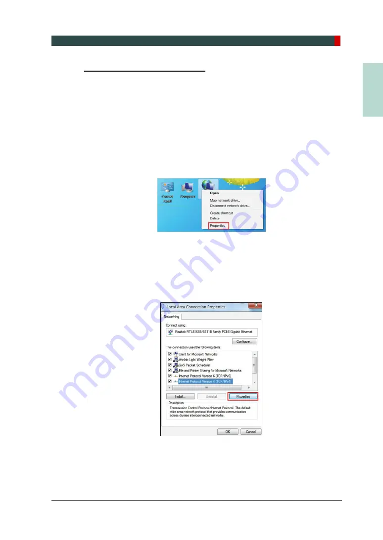
8.  From the following figure, select the 

Internet Protocol Version 4

 and click on 

Properties


Figure 7-40. Internet Protocol Version 4 

9.  To set the new IP address, enter the IP address ‘192.168.33.87’, and click on 

OK

10.  Reset the PC and the equipment. 

Содержание Green 21 PCT-90LH

Страница 1: ...User Manual Model PCT 90LH Version 1 49 Full version English...

Страница 2: ......

Страница 3: ...ew of this manual is recommended before installation to ensure proper installation of this equipment The Green 21 Model PCT 90LH is in steady improvement The information contained in this manual may b...

Страница 4: ...re Failure to comply with a warning may result in severe damage to the equipment or physical injury to the operator and or patient CAUTION Indicates a situation that demands prompt and careful action...

Страница 5: ...Conventions Used in this Manual Green21 Model PCT 90LH Installation Manual iii ENGLISH This Page Left Blank Intentionally...

Страница 6: ...ment install the device on a flat surface to maintain stability If the equipment is not stable property damage and or personal injury may occur DO NOT push or pull the equipment Make sure the X ray al...

Страница 7: ...not connect any items or equipment to this system which are not part of the system IEC60601 1 1 3rd edition 2005 6 Any equipment not approved by VATECH must comply with the applicable standards IEC 60...

Страница 8: ...ities to verify that all applicable radiation safety requirements are met 3 This equipment should not be installed in the immediate vicinity of other devices 4 Do not install the equipment in an area...

Страница 9: ...n21 Model PCT 90LH Installation Manual vii ENGLISH Before installation unload the Rotating Unit and place it on the floor as shown in the following figure To install the equipment safely at least thre...

Страница 10: ...Important Precautions viii Green21 Model PCT 90LH Installation Manual Locations of the Main Power and the Emergency Stop Switches Main Power Switch Emergency Stop Switch...

Страница 11: ...n Site 7 2 1 Room Requirements 7 2 2 Electrical Requirements 9 2 3 Exposure Switch Installation Options 9 3 Before the Installation 11 3 1 Labor 11 3 2 Required Tools 11 3 3 Unpacking the Boxes 13 3 4...

Страница 12: ...off the Firewall 64 6 3 Setting up the Power Management Options 65 6 4 Turning off the User Account Control 67 6 5 Setting Folder Exclusions with Anti Virus Software 68 7 Installing Software 69 7 1 B...

Страница 13: ...Table of Contents Green21 Model PCT 90LH Installation Manual 1 ENGLISH This Page Left Blank Intentionally...

Страница 14: ...0 Table of Contents 2 Green21 Model PCT 90LH Installation Manual This Page Left Blank Intentionally...

Страница 15: ...ied technician s from one of our authorized agents The equipment has been used under a normal condition in accordance with the user s manual 1 2 Customer s Responsibility Site planning and preparation...

Страница 16: ...r connected to the Main Power Switch Main Power Switch Type B Applied Equipment IEC60601 1 Degree of protection against leakage current and or electric shock Class 1 equipment Label Radiation hazard L...

Страница 17: ...e disposed of as unsorted municipal waste and must be collected separately Label Warns ESD hazard MCU board Board package Indicates that this equipment is classified as a CLASS 1 LASER PRODUCT in acco...

Страница 18: ...Ib equipment and obtained CE marking in April 2007 for regulations compliance in accordance with the revised European Union s MDD Medical Devices Directive 93 42 EEC MEDICAL EQUIPMENT WITH RESPECT TO...

Страница 19: ...out the patient as possible 2 This equipment should not be installed on thick carpets for stability reasons 3 Anti static floor materials should be used around the equipment 4 The PC monitor emergency...

Страница 20: ...than 800 mm 31 wide 3 Floor area The floor of the X ray room must be stable and level for system balance The floor must be able to support a minimum weight of 500 kg m2 110 lbs feet2 4 Protection agai...

Страница 21: ...SO Whenever possible use different power outlets for each device If a multiple portable socket outlet MPSO must be used ensure that the PC and equipment are connected to the same MPSO Use a dedicated...

Страница 22: ...The exposure switch holder is mounted on the wall 3 The 3rd party exposure switch not VATECH s is used on demand of the customers For this scenario follow the procedures as described below Cut the exp...

Страница 23: ...least three installers are required 3 2 Required Tools The following tools are required to install the equipment Item Figure Size Wrench set 1 5 mm 10 mm 0 05 0 4 Monkeywrench 10 Ratchet wrench Tips 3...

Страница 24: ...3 Before the Installation 12 Green21 Model PCT 90LH Installation Manual Item Figure Size Hammer Multi meter Hammer drill Cutting pliers...

Страница 25: ...y agent or VATECH Wear the ant static or general purpose gloves 3 4 Package Size The package sizes have been measured including the palettes 1 Base Packing Item Size Weight Length 1 240 mm 48 8 208 kg...

Страница 26: ...YES NO 4 PC Box 1 Option YES NO 5 Accessory Box 1 YES NO 6 Monitor 1 Option YES NO 7 Cover Bottom Left 1 YES NO 8 Cover Bottom Right 1 YES NO 9 Cover Back Bottom 1 YES NO 10 Headrest Assay 1 YES NO 11...

Страница 27: ...3 Before the Installation Green21 Model PCT 90LH Installation Manual 15 ENGLISH 3 5 1 Location Layout of the Parts and Accessories...

Страница 28: ...uals User Manual 1 YES NO Installation Manual 1 YES NO Easy Dent or EzDent I Manual 1 YES NO Ez3D plus or Ez3D I Manual 1 YES NO Wheelchair Height Limit Label 1 YES NO Installation CD or USB 1 YES NO...

Страница 29: ...Up Down Switch Chinrest Up Down Switch Chinrest Up Down Switch Holder 1 YES NO Double Sided Sticker 1 YES NO Flat Head Bolt M3 x 8 2 YES NO 6 Anti static gloves 1 YES NO 7 Chin Block HIGH 1 YES NO 8...

Страница 30: ...irmed 13 Headrest Cradle 1 YES NO 14 Blank 15 Blank 16 Silicon Cap 18 YES NO 17 Base Cap 6 YES NO 18 Vertical Cap 4 YES NO 19 Wrench Bolt M3 x 6 2 YES NO 20 Cable Tie L 100mm 10 YES NO 21 IFG Card or...

Страница 31: ...10 Nut 10 YES NO 24 Wrench Bolt M10 x 60 2 YES NO 25 Wrench Bolt M10 x 40 w spring and flat washer 6 YES NO 26 Wrench Bolt M10 x 30 w spring washer 4 YES NO 27 Truss Screw M4 x 8 14 YES NO 28 Connecto...

Страница 32: ...3 Before the Installation 20 Green21 Model PCT 90LH Installation Manual This Page Left Blank Intentionally...

Страница 33: ...on Manual 21 ENGLISH 4 Installation Procedures 4 1 Installing the Column Unit 1 Put the Column Unit on the floor Figure 4 1 Placement of the Column Unit 2 Remove the Transfer Handle from the Column Un...

Страница 34: ...bottom of the Column Unit Wrench Bolt Part No No 24 Size M10 x 60 Qty 2 EA Figure 4 3 Putting two wrench bolts into the holes Put the bolts into the holes until about 35mm is left outside 4 Attach the...

Страница 35: ...the rear to tie it up and work around the cable to prevent it from being pushed When connecting the base unit the base unit may hang on the bundled cable exposed in the column Make sure that use a ca...

Страница 36: ...24 Green21 Model PCT 90LH Installation Manual Figure 4 5 Putting the wrench bolts and tightening them 6 Hold the Upper Handle and stand the equipment up vertically Figure 4 6 Standing the equipment u...

Страница 37: ...the bracket Figure 4 7 Removing the bracket 8 Unscrew the bolts on the left and right sides and remove the Upper Handle When removing the shrink wrap first and remove the handlebar bolt the bolt can b...

Страница 38: ...rew the transfer screws and labels shown in the following figure since they have been tightened only for transfer Figure 4 8 Removing the transfer screws and labels Figure 4 9 After removal of the tra...

Страница 39: ...ith the Column Unit as shown below At least three installers are required for this step Figure 4 10 Assembling the Rotating Unit with the Column Unit 2 Tighten five bolts with ten nuts as shown below...

Страница 40: ...ion Manual 3 Remove the Transfer Handle from the Rotating Unit Figure 4 12 Removing the transfer handle 4 Connect the cables to the Rotating Unit referring to Section 4 4 1 5 Unscrew two bolts in the...

Страница 41: ...29 ENGLISH 6 Remove the transfer screws with labels and spacers Check if they have been correctly removed as shown below Figure 4 14 Checking removed screws with labels and spacers DO NOT perform the...

Страница 42: ...Handle frame knob locking is released so that the damage will be reduced even if there is an impact outside the packing box 1 Put the Handle Frame into the Base Unit and tighten two bolts on the fron...

Страница 43: ...31 ENGLISH 2 Tighten two bolts on the rear side as shown in the following figures Wrench Bolt Part No 26 w spring Size M10 x 30 Qty 2 ea Figure 4 16 Tightening two bolts on the rear side 3 Connect th...

Страница 44: ...el PCT 90LH Installation Manual 4 3 2 Installing the Chair 1 Turn on the system and raise the Column Unit with the Rotating Unit to assemble the Chair 2 Assemble the Chair with the Column Unit as show...

Страница 45: ...33 ENGLISH 4 4 Connecting the Cables 4 4 1 Connecting the Cables to the Rotating Unit 1 Check if there are six cables before performing the connection Figure 4 18 Checking cables USB is not connected...

Страница 46: ...er cables including USB cable to the top of the Rotating Unit as shown below Refer to the Cable Information in Table 4 1 Figure 4 19 Connecting the cables to the Rotating Unit After connecting the Cab...

Страница 47: ...1715A ROTATOR POWER SIGNAL CABLE 1 1 4 4 2 Connecting the cables to the Handle Frame Connect the cables to the rear side of the Handle Frame Refer to the Cable Information in Table 4 2 Figure 4 20 Con...

Страница 48: ...pment 1 Place the spirit level for leveling the front rear on top of the Rotating Unit as shown below Figure 4 21 Leveling the front rear 2 Adjust the level foot on the Base Unit until the bubble in t...

Страница 49: ...4 Installation Procedures Green21 Model PCT 90LH Installation Manual 37 ENGLISH 3 For leveling the left right place the spirit level as shown below Figure 4 22 Leveling the left right 4 Repeat Step 2...

Страница 50: ...over on the rear side of the Handle Frame by tightening two screws Truss Screw Part No 27 Size M4 x 8 Qty 2 ea Figure 4 23 Assembling the cover on the Handle Frame The USB cable from the Handle Frame...

Страница 51: ...tion Manual 39 ENGLISH Assemble the covers on the Base Unit by tightening five wrench bolts Make sure to use wrench bolts for assembling the Base Unit s covers Wrench Bolt Part No 29 Size M4 x 12 Qty...

Страница 52: ...attach the covers on the left right bottom and rear sides Tighten four truss screws on the bottom right side first as below and repeat the same procedure for the bottom left side Truss Screw Part No 2...

Страница 53: ...Model PCT 90LH Installation Manual 41 ENGLISH Finally assemble the rear cover of the Rotating Unit by tightening seven screws Pan Head Screw Part No 30 Size M4 x 8 Qty 7 ea Figure 4 26 Assembling the...

Страница 54: ...anual Assemble the rear cover of the Column Unit and tighten four screws on the left and right sides of the cover Truss Screw Part No 27 Size M4 x 8 Qty 4 ea Assemble the rear cover Left side of the c...

Страница 55: ...just the Chinrest checking the image 4 8 Checking Chinrest Block Alignment Check that the position of the chinrest block is out of the criteria value Criteria The end of the Bite block is located at 1...

Страница 56: ...hinrest limit 4 Down limit setting i Place the Chinrest at the Lowest using the LCD button ii Chinrest Lowest limit setting SPM_CRDL iii Place the Column at the Lowest using the LCD button iv Column L...

Страница 57: ...the topmost using the LCD button ii Column Topmost limit setting SPM_CLUL iii Place the Chinrest at the Topmost using the LCD button iv Chinrest Topmost limit setting SPM_CRUL v Rotator 90 degree posi...

Страница 58: ...Carbon Cover Make sure the X ray align is correct The criteria for left right top and bottom are as follows 1 CT Threshold 95 Collimator Min Max Left T 80 6 pixels 8 pixels Right T 80 4 pixels 6 pixe...

Страница 59: ...OJ_4 cut 4 Run C VCaptureSW Exe VCaptureSW exe file and select FOV 21x19 then shoot No Reconfiguration Required When performing the collimator correction wait for 10 minutes after performing one CT se...

Страница 60: ...aptureSW Exe VCaptureSW exe file and select FOV 21x19 then shoot No Reconfiguration Required When performing the collimator correction wait for 10 minutes after performing one CT sequence shot and the...

Страница 61: ...r PROJ_4 cut Backup folder PROJ_Velo Left side Right side Collimator Program Rotator not working shooting ex PROJ_4 cut X axis 61 pixels X axis 164 pixels NCSW Program Rotator working shooting ex PROJ...

Страница 62: ...t digit 3 Run C VCaptureSW Exe VCaptureSW exe file and select FOV 21x19 then shoot No Reconfiguration Required When performing the collimator correction wait for 10 minutes after performing one CT seq...

Страница 63: ...collimator to its own criteria and click CALC to set the 17x15 12x9 8x8 collimator Collimator value should be saved after proceeding to Capture after clicking the Initial button so Should shoot more t...

Страница 64: ...V 4 Child mode is set to the calculated value when clicking CALC button after completing Adult mode 7 Ceph except Carpus 4 cut align work 1 Perform 4 cut according to the following criteria Ceph LAT P...

Страница 65: ...290 pixels Bottom T 80 15 pixels 30 pixels 2 Run C VCaptureSW Util CollimatorAlign CollimatorAlign exe file Collimator value should be saved after proceeding to Capture after clicking the Initial butt...

Страница 66: ...g that the number of acquired projections is 5401 change the PROJ folder to PROJ_Air_1 3 Take 3 shots in the same way as above PROJ folder names are stored as PROJ_Air_1 PROJ_Air_2 and PROJ_Air_3 resp...

Страница 67: ...ation Procedures Green21 Model PCT 90LH Installation Manual 55 ENGLISH Check UseAirCal 1 in the C VCaptureSW Acquisition CBCT WidePano RE C L2setting vxm file 0 No aircal 1 Aircal applied Same as ENCT...

Страница 68: ...4 Installation Procedures 56 Green21 Model PCT 90LH Installation Manual This Page Left Blank Intentionally...

Страница 69: ...l 57 ENGLISH 5 Setting up PC 5 1 Direct Connection Diagram Figure 5 1 Direct Connection Diagram Fiber Optic Cable Used to transfer image data to the PC Warning System Panel Used to provide a visible i...

Страница 70: ...at the equipment is installed in the area with an unstable electric power supply using the AVR Automatic Voltage Regulator is strongly recommended to keep the line voltage stable The PC system provide...

Страница 71: ...ional Recommended system HP Z440 It is mandatory to meet the PC system requirements specified in the table above 5 3 Recommended UPS Specification Option An uninterruptible power supply UPS is an elec...

Страница 72: ...r 3 Insert the grabber card carefully into the x16 slot as shown below and lock it Figure 5 2 Location of the grabber card Double check the locking status between the board and its holder after the bo...

Страница 73: ...es such as a keyboard mouse and video cables The following figures and descriptions are based on the PC model Z420 from HP 1 Connect the Ethernet Optic cable and USB cable between the connectors of th...

Страница 74: ...sert the 3D viewer USB key into the USB port Figure 5 4 Inserting the 3D viewer USB key Connecting the Exposure switch cable Figure 5 5 Connecting the Exposure switch cable Table 5 2 Cable Information...

Страница 75: ...viewer USBipulation of images should be installed on the formatted PC where no other program s except the operating system OS is present Before InstallShield installation ensure that the video card d...

Страница 76: ...sion For this reason it is required to disable the Windows Firewall by using the following procedures 1 Open the Start screen type Windows Firewall in the search box 2 Click the Windows Firewall icon...

Страница 77: ...ns To avoid disruptive and abnormal operation while acquiring an image it is required to reconfigure some parameters on the Windows operating system Disable the Screen Saver 1 Open the Start screen ty...

Страница 78: ...nual Selecting the Power Options Monitor and System 1 Open the Start screen type Power Options in the search box 2 Click Choose when to turn off the display 3 Select Never for both Turn off the displa...

Страница 79: ...90LH Installation Manual 67 ENGLISH 6 4 Turning off the User Account Control 1 Open the Start screen type User Account Control in the search box 2 Disable the UAC by moving the slider bar down to the...

Страница 80: ...performed by the anti virus software For the Green21 the following folders and files inside for relevant software should be excluded with the virus scan Path Software C ProgramFiles Vatech EzDent i Ea...

Страница 81: ...tive manuals Before InstallShield installation ensure that the video card driver installed on PC is the most up to date version To check this go to the Website www nvidia com Perform virus scan for th...

Страница 82: ...as an accessory Please check the serial number txt e g 047 011752 txt file 1 Turn on the PC and the Equipment 2 Insert the CD into CD ROM drive or connect the USB Drive to the USB connector and perfo...

Страница 83: ...nstallation Manual 71 ENGLISH 5 Select the Model and click on Next Figure 7 3 Selecting the Model 6 Select the Modality and click on Next Note that if the CEPH feature comes with the equipment also ch...

Страница 84: ...7 Installing Software 72 Green21 Model PCT 90LH Installation Manual 7 Select the CT sensor type WidePano and click on Next Figure 7 5 Selecting the CT sensor type...

Страница 85: ...l PCT 90LH Installation Manual 73 ENGLISH 8 Select the PANO sensor type WidePano and click on Next Figure 7 6 Selecting the PANO sensor 9 Optional Select the CEPH sensor WidePano and click on Next Fig...

Страница 86: ...umber COM4 and click on Next Select the port No COM4 The same COM port No should be used between the equipment and PC 11 Select the language and click on Next 12 Select the third party software in use...

Страница 87: ...ding to the product options Touch LCD Auto Save and Frame Grabber Type Note that the acquired image data is saved automatically when the Auto Save is checked Figure 7 9 Selecting additional options 14...

Страница 88: ...Installation Manual 15 The following figure displays the information entered so far If necessary you can modify it by clicking on Back Figure 7 11 Ready to begin installing 16 Click on Install to con...

Страница 89: ...LISH 7 4 1 Installing the DICOM Viewer 1 Click on Next to install the DICOM viewer Figure 7 13 Starting installation 2 Read the following license agreement and select I accept the terms of the license...

Страница 90: ...tallation Manual 3 Enter the User Name and the Company Name and click on Next Figure 7 15 Entering the User Name and the Company Name 4 Click on Install After it is completed click on Finish to exit t...

Страница 91: ...talling the DirectX 1 To install the DirectX select I accept the agreement and click on Next to continue Figure 7 17 Starting installation of DirectX 2 Wait until it is completed Figure 7 18 During th...

Страница 92: ...the Frame Grabber Virtual Serial 1 x Inform Grabber 1 After completing Direct X installation Virtual Serial 1 x installation will be started Click Install in the Welcome window 2 During installation V...

Страница 93: ...When Microsoft Visual C 2010 x64 Redistributable installation window appears click Install to continue the process and click Finish when completed 6 Optional When Microsoft NET Framework 4 x x install...

Страница 94: ...After completing Direct X installation Grabber Driver Setup will be started Select the language in the installer language window and press the OK button 2 When the Grabber Driver Setup window appears...

Страница 95: ...appear and disappear and the Completing Grabber Driver Setup window will appear Choose the Reboot now or I want to reboot later and click the button manually If an error occurs during installation it...

Страница 96: ...7 4 4 Finalizing Installation The installation has just been completed Click on Finish and restart PC 7 4 5 Verifying Installation 1 Locate the file Green21_Install_Log txt on the Desktop 2 Open it t...

Страница 97: ...to finish the uninstallation 7 6 Setting up the User specific Information Only when using Console program with automatic interworking function and EzDent i program the automatic interworking function...

Страница 98: ...lick on EzDent i Setting Figure 7 21 Settings for EzDent i 2 Click on Acquisition Console Program 3 Make sure that the console program settings are as follows Console Program Path C VCaptureSW exe VCa...

Страница 99: ...follow the procedure outlined below EzDent i 1 Click the PATIENT tab and click the Add Patient icon from the main GUI window 2 Enter the required patient information Chart Number First Name and Last N...

Страница 100: ...imaging mode selection buttons appear Figure 7 22 Starting ACQUISITION 2 Select the imaging mode Then the main GUI in the selected imaging mode appears Figure 7 23 Selecting the imaging mode The imag...

Страница 101: ...From the main GUI window click on the icon in the red box Figure 7 24 Clicking on the icon for settings 2 Select Engineer and type the password vatech and then click on Log In Figure 7 25 Typing the p...

Страница 102: ...and DAP Unit are displayed in the DAP Figure 7 28 Checking the default DAP Level and DAP Unit 6 In the Language Option change the language if necessary and click on Machine Set Figure 7 29 Changing th...

Страница 103: ...ual 91 ENGLISH 8 In the Patient information setting configure Link type and file path as shown below Figure 7 31 Patient information setting 9 In the Link information setting configure Link type and f...

Страница 104: ...92 Green21 Model PCT 90LH Installation Manual 10 Click on Default tab and configure the user defined parameters Figure 7 33 Default tab 11 Click on Save if the settings have been completed Figure 7 3...

Страница 105: ...er the equipment is turned on 1 Click on the General tab in the control panel 2 In the Networking option select the Serial checkbox and set Serial port and Baud Rate as follows and then click on Manag...

Страница 106: ...the packing mode Now note that the equipment is out of the packing mode To re enter the packing mode use the command PKEN_0001 Figure 7 36 Exiting the packing mode 5 Click on Exit and terminate the co...

Страница 107: ...nouncement mode Division 0000 CT PANO Music Different for each mode 0001 CT PANO Music The same for each mode 0002 Default CT PANO Beep The same for each mode 1 Send the command in accordance with the...

Страница 108: ...96 Green21 Model PCT 90LH Installation Manual When the same music announcement is desired for CT and PANO imaging modality enter the command MPOP_0002 in the command field and click on Send Figure 7 3...

Страница 109: ...e PC the proper IP address should be set on the PC The following screenshots are taken in the Windows 7 5 From the desktop right click on the Network icon and click on Properties Figure 7 39 Network P...

Страница 110: ...he test image acquisition after the software is installed 2 Acquire a test image using the phantom jig For further details about the image acquisition refer to the system User Manual For other issues...

Страница 111: ...8 Acquiring a Test Image Green21 Model PCT 90LH Installation Manual 99 ENGLISH This Page Left Blank Intentionally...

Страница 112: ...ications 9 1 Dimension unit mm Item Description Weight 321 kg 708 lbs with the Base Total Height Max 2185 mm 86 0 inch Rotating Unit Vertical Movement Max 680 mm 26 8 inch Dimension Length x Width x H...

Страница 113: ...uirement 10 Mode of operation non continuous operation NFPA 70 long time operation needs waiting time at least 60 times the exposure time before the next exposure begins Exposure time Max 18 s Resting...

Страница 114: ...tallation Manual 9 3 Environmental Specifications Item Description During operating Temperature 10 35 Relative humidity 30 75 Atmospheric pressure 860 1060 hPa Transport and storage Temperature 10 60...

Страница 115: ...9 Technical Specifications Green21 Model PCT 90LH Installation Manual 103 ENGLISH This Page Left Blank Intentionally...

Страница 116: ...Name of Clinic or Hospital Address Phone E Mail Website Information about the equipment seller Dealer Name of dealer Address Phone E Mail Website 2 Installation information Installation information A...

Страница 117: ...list While installing equipment Yes No Is the room large enough 2 500mm L x 2 000mm W x 2 500mm H 98 L x 79 W x 98 H Is the door entrance wider than 800mm 31 Is there a radiation protection plan on th...

Страница 118: ...d not damaged Was the equipment well balanced 6 After installation After installation Checklist Yes No Is the equipment ready for normal customer operation Has the installation area been cleaned up af...

Страница 119: ...the X ray shield room Hceiling Raise the Rotating Unit to the maximum height and check if the wheelchair height limit label is in the right spot IMPORTANT The height from the floor to the wheelchair...

Страница 120: ...is not located in the right spot detach it and attach the new label provided by VATECH If it is hard to detach the label because most part of the label is covered under the lower column part you need...

Страница 121: ...of the equipment when the column is fully extended d Hceiling HMax Hceiling 2 185 mm default max height For example if Hceiling is 2 150 mm Hscrew height value is calculated as follows d Hceiling HMax...

Страница 122: ...umn Unit until the height from the floor to the bottom line of the Rotating Unit becomes about 1 539 mm 2 Remove the lower rear cover of the Column Unit Perform 1 Unscrew two screws and remove the dec...

Страница 123: ...ix ENGLISH 2 Unscrew six screws and remove the lower rear cover as shown in the following figures 3 Unscrew twelve screws and remove the upper rear cover of the Column Unit as shown in the following f...

Страница 124: ...Appendix 4 Lower the Column Unit to the 300 mm point from the bottom line of the Rotating Unit Perform the next step Adjusting the Limit Block on page 90 300 mm...

Страница 125: ...st the Limit Block from the default current position to a new one 1 Check the Limit Block s default current position 2 Unscrew two screws in the Limit Block and move the Limit Block up to lower the co...

Страница 126: ...st current information contact your VATECH representative Manufactured by VATECH Co Ltd Tel 82 1588 9510 Email gcs vatech co kr Website http www vatech com Headquarters 13 Samsung 1 ro 2 gil Hwaseong...

Страница 127: ......

Страница 128: ......

Отзывы: