background image


CP-3800 GC Operator’s Manual


89


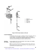
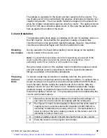
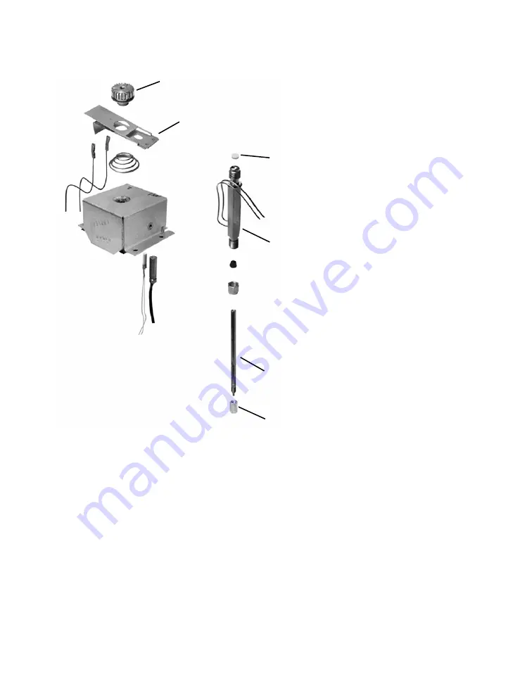
Figure 9 1041 Universal Injector with Insert 

Column Installation 

The following instructions apply to installing a 0.53 mm ID capillary column in 
the 1041 injector.  Note that the thin polymeric coating on fused silica 
columns will give some protection against breakage; however, fused silica 
columns are somewhat fragile and must be handled with care. 


Mounting 
the Column 

During operation, the 0.53 mm ID capillary column hangs on the capillary 
column holder in the column oven.  

Note: 

To prevent the column from unwinding, weave both of the column ends 

through and around the column loop several times. This is particularly useful if 
your column is not mounted in a cage. 

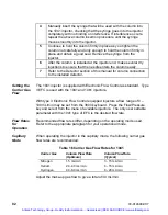
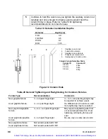
1 Septum 

Nut 

Automatic Start Switch 

3 Septum 
4 Injector 

Body 

5 Injector 

Insert 

6 Capillary 

Nut 

Artisan Technology Group - Quality Instrumentation ... Guaranteed | (888) 88-SOURCE | www.artisantg.com

Содержание CP-3800 GC

Страница 1: ...nderutilized and idle equipment along with credit for buybacks and trade ins Custom engineering so your equipment works exactly as you specify Critical and expedited services Leasing Rentals Demos In...

Страница 2: ...ator s Manual 3800 Keyboard and Display Sample Introduction Detectors Communications Local Automation Varian Inc 2700 Mitchell Drive Walnut Creek CA 94598 1675 usa Artisan Technology Group Quality Ins...

Страница 3: ...Artisan Technology Group Quality Instrumentation Guaranteed 888 88 SOURCE www artisantg com...

Страница 4: ...External Sample Introduction Systems 50 Pneumatic Systems 50 The CP 1177 Split Splitless Capillary Injector 51 Features of the CP 1177 injector 51 Automatic Start Switch 52 CP 1177 Injector Assemblys...

Страница 5: ...41 Injector 94 The 1061 Flash Vaporization Injector 95 Automatic Start Switch 96 Injector Assembly and Insert 96 Column Installation 97 1061 Operation 99 Testing the 1061 Injector 101 Valved Systems 1...

Страница 6: ...ustrations Figure 1 CP 1177 Injector Assembly 52 Figure 2 CP 1177 Injector Flow Path 55 Figure 3 Type 1 EFC Flow Diagram 56 Figure 4 1079 Injector Capillary Installation 57 Figure 5 1079 Injector Asse...

Страница 7: ...Connection 156 Figure 24 10Base2 Ethernet Components 157 Figure 25 3800 GC to Star Workstation Connection 157 Figure 26 Acceptable and Unacceptable Disconnection Examples 158 Figure 27 Complex 3800 G...

Страница 8: ...olumn Injection 86 Table 13 Large Volume Injection 87 Table 14 1079 Test Samples 87 Table 15 General Tightening and Retightening for Common Ferrules 91 Table 16 Carrier Gas Flow Rates for 1041 92 Tabl...

Страница 9: ...vi 03 914648 00 7 Artisan Technology Group Quality Instrumentation Guaranteed 888 88 SOURCE www artisantg com...

Страница 10: ...in up to 11 lines of text Generally all information pertaining to a specific component or function is presented on a single page However two or more pages are used for some functions such as building...

Страница 11: ...ited method must be activated After editing a method you must activate it to ensure its parameter settings are used during the next analysis Each 3800 screen has a prompt line directly beneath the met...

Страница 12: ...ign and infinity increment INCR and decrement DECR keys and the ENTER key The HELP key gives a context sensitive explanation for the parameter that the cursor is on Instrument Contains the Setup and S...

Страница 13: ...the field is updated to the new parameter setting and the cursor moves to the next available field The up and down cursor keys can also be used to move through a list of numbered menu items Selecting...

Страница 14: ...ce it with the previous parameter as long as the ENTER key has not been pressed INCR DECR Used to select a specific value when the choices are a defined set of possible values e g detector attenuation...

Страница 15: ...as a column or a field upgrade is done or an option is removed The hardware installed on the GC must match the information in SETUP therefore if a hardware change is made then the appropriate change...

Страница 16: ...format and the language for display is also performed here HEATED ZONES The 3800 has six available heated zones excluding the column oven see figure below These are numbered 1 6 with all zones having...

Страница 17: ...50 C1 Location Front Front Middle Rear Coolant None None LN2 LCO2 EFC The 3800 GC can be configured with either manual pneumatics or electronic flow control EFC Nine types of EFC modules exist and eac...

Страница 18: ...such as a run start or another method activation occurs before the Gas Saver Timeout is reached then the system will reduce the flow through the system to the Gas Saver Flow The GC will advance to a f...

Страница 19: ...tlet Pressure Atm if the column exit is to atmospheric pressure Vacuum if the column is connected to a vacuum source e g Varian Mass Spectrometer Pressure Display Units psi bar kPa depending on which...

Страница 20: ...tector FID Channel 1 Gas Type He make up Channel 2 Gas Type H2 Channel 3 Gas Type Air AutoCalibrate Save and Exit For this Parameter Enter Channel 1 Gas Type He N2 or Ar Type 11 EFC has the following...

Страница 21: ...r TSD Channel 1 Gas Type He make up Channel 2 Gas Type H2 Channel 3 Gas Type Air AutoCalibrate Save and Exit For this Parameter Enter Channel 1 Gas Type He N2 or Ar Type 12 EFC has the following softk...

Страница 22: ...this Parameter Enter Channel 1 Gas Type He N2 or Ar Type 13 EFC has the following softkeys Press this softkey If you want to AutoCalibrate Automatically calibrate the EFC system When it is finished a...

Страница 23: ...2 Gas Type He reference AutoCalibrate Save and Exit For this Parameter Enter Channel 1 Gas Type He N2 or Ar Make up Channel 2 Gas Type He N2 or Ar Make up or reference Type 14 EFC has the following so...

Страница 24: ...el 1 Gas Type Air 1 Channel 2 Gas Type H2 Channel 3 Gas Type Air 2 AutoCalibrate Save and Exit Type 15 EFC has the following softkeys Press this softkey If you want to AutoCalibrate Automatically cali...

Страница 25: ...ke up Channel 2 Gas Type H2 reference AutoCalibrate Save and Exit For this Parameter Enter Channel 1 Gas Type Make up or reference Channel 2 Gas Type Make up or reference Type 16 EFC has the following...

Страница 26: ...lculations If a packed column is used then 0 is set for length and ID The parameters and their ranges are shown below Default Range Location Front Front Middle Rear Carrier Gas He He H2 N2 Length mete...

Страница 27: ...table of 22 names When a name is chosen this also defines the default states of the valve These states will be visible when the valve is being programmed in the valve table section of the 3800 method...

Страница 28: ...FF ON Event C EC OFF ON Event D ED OFF ON None Ethernet Setup If you are connecting your 3800 to a company network you can enter an IP Address Netmask and Default Gateway provided by your company netw...

Страница 29: ...ADY is displayed next to the component while if a fault is present the message FAULTED appears The Column Oven field also indicates when it is stabilizing Miscellaneous Setup Parameters Is Ready In a...

Страница 30: ...l Standby Mode 8400 Miscellaneous and Column Mode Each of these four items are discussed below The Remote Local screen allows you to select between remote Star Workstation or local control Disabling r...

Страница 31: ...e of zero disables the standby temperature function 8400 Miscellaneous allows you to turn the autosampler buzzer On Off change the plunger stroke warning limit turn the vial detector On Off and Find h...

Страница 32: ...een method numbers then press the Activate Now softkey to activate the method The Activate Now softkey is disabled while local automation is running Below is an example of the Activate Method screen A...

Страница 33: ...so that the desired injector may be selected for editing Method components appear in the following order Injector Flow Pressure Column Oven Detector and Output If you want to go directly to one of the...

Страница 34: ...s you to copy the contents of one method to another However a method that is currently running cannot be overwritten i e another method cannot be copied to it Follow the instructions shown in the scre...

Страница 35: ...1 0 00 20 00 PRESET TO DEFAULTS Method Name Method 1 Preset New Lock Unlock Methods This allows you to prevent unauthorized changes to a method ACTIVE METHOD EDIT METHOD CTRL RUN TIME END TIME Method...

Страница 36: ...appears type a number between 0 and 999 999 then press the Toggle Lock softkey The method status will change from Unlocked to Locked To unlock a locked method follow the same procedure typing in the p...

Страница 37: ...SAMPLE DELIVERY 1 8200 2 Valve Table Valve Table The following method screens show an example of a 3800 configuration with two automated gas sampling valves installed in a valve oven and two manual p...

Страница 38: ...le ACTIVE METHOD EDIT METHOD CTRL RUN TIME END TIME Method 1 Method 1 0 00 20 00 Valve State 4 RSV ON 1 GSV Fill 5 None 2 GSV Fill 6 None 3 FSV ON 7 None VALVE TABLE Time 1 GSV 2 GSV 3 FSV 4 RSV 5 Non...

Страница 39: ...mn 1 Column 2 Simultaneous Injection SI Fill Inject Methanizer Bypass MB Series Bypass Sample Preconcentration Trap SPT SPT Desorb SPT Trap External Event A EA OFF ON External Event B EB OFF ON Extern...

Страница 40: ...al heated zones You will be presented with a menu when the INJECTOR key is pressed if more than one injector is installed and configured in Instrument SETUP For example a 3800 with a CP 1177 in the fr...

Страница 41: ...ature control 2 Split state programming if type 1 EFC is installed If the CP 1177 has manual pneumatics then the split valve is programmed in the valve table located in SAMPLE DELIVERY The following a...

Страница 42: ...d the entire sample vapor should enter the column After 0 75 minutes the split state is switched to ON with a 100 1 split ratio ACTIVE METHOD EDIT METHOD CTRL RUN TIME END TIME Method 1 Method 1 0 00...

Страница 43: ...cal method parameters for a 1079 with cryogenics and temperature programming Temperature programs are entered in page 1 ACTIVE METHOD EDIT METHOD CTRL RUN TIME END TIME Method 1 Method 1 0 00 20 00 Se...

Страница 44: ...re or 2 it reaches the set temperature and the GC does not go into run The valve will be turned off if the coolant time out is reached and no further coolant will be applied A value of zero disables t...

Страница 45: ...eumatics then the injector split state is programmed in the VALVE TABLE of the SAMPLE DELIVERY section Isothermal 1041 1061 Injector The 1041 and 1061 isothermal injectors display one screen to set th...

Страница 46: ...E Key The FLOW PRESSURE section displays the Electronic Flow Control status or method parameters for injectors and valves controlled by EFC modules Three types of EFC modules exist all are described i...

Страница 47: ...D CTRL RUN TIME END TIME Method 1 Method 1 0 00 20 00 Col Press psi 10 0 Col Flow mL min 2 0 Linear Vel cm sec 3 5 Total Flow mL min 50 Split Ratio Off FRONT EFC Type 1 Page 1 of 2 Step Pres psi Rate...

Страница 48: ...s Saver flow rate will be started A message will be logged in the instrument log The fault is cleared by activating a method EFC setup for type 1 modules CP 1177 and 1079 injectors also contains a sep...

Страница 49: ...en in Setup actual flow rate calculated linear velocity The table below is the method parameters to establish the carrier flow into the injector column system ACTIVE METHOD EDIT METHOD CTRL RUN TIME E...

Страница 50: ...low rate In this example the column head pressure is held constant during the analytical run but the total flow into the system is increased significantly at the beginning of the run to allow the syst...

Страница 51: ...bilization time Similar to other programming tables the initial or isothermal line will always appear on the first line of the table You can then build a temperature program by adding new lines Below...

Страница 52: ...installed detectors The menu screen indicates the name of the detector and its location Below is an example for a Flame Ionization Detector Further details for programming other detectors can be found...

Страница 53: ...l C 300 Signal mV 5 15 FRONT FID Page 1 of 2 Oven Power ON Temperature C 300 Electronics ON Range 12 IGNITE AUTOZERO ADJUSTMENTS The IGNITE softkey applies power to the FID ignitor filament for 5 seco...

Страница 54: ...Default Range Time Initial 0 00 999 99 Range 12 9 10 11 12 A Z No yes no set to yes at initial time means that FID A Z is on continuously before the run starts Press the Adjustments softkey to access...

Страница 55: ...up Flow 25 ml min 0 50 ml min H2 Flow 30 ml min 0 50 ml min Air Flow 300 ml min 0 500 ml min METHANIZER A methanizer is an option that converts carbon monoxide and carbon dioxide to methane It is ass...

Страница 56: ...20 00 OUTPUT MENU 1 Program Analog Output Port A 2 Program Analog Output Port B 3 Program Analog Output Port C By selecting Analog Output A above the following screen appears You can time program the...

Страница 57: ...48 03 914648 00 7 Artisan Technology Group Quality Instrumentation Guaranteed 888 88 SOURCE www artisantg com...

Страница 58: ...cryogenics 3 The 1041 On Column Injector is designed for use with largebore capillary columns or packed columns The standard injector is supplied with an adapter for largebore capillary columns Optio...

Страница 59: ...1177 Liquid Injector Type 1 EFC Manual pneumatics inlet flow controller back pressure regulator with pressure gauge 1079 Liquid Injector Type 1 EFC Manual pneumatics inlet flow controller back pressur...

Страница 60: ...thermally from 50 to 450 C Changing from one injection mode to another typically involves a change of injector insert and a modification to the injector and EFC program Glass inserts can be easily cha...

Страница 61: ...ringe barrel or manually pressed at the moment of sample injection The GC run can also be manually started by pressing START on the keyboard The injector nut and automatic start switch assembly may be...

Страница 62: ...pen 2 0 mm ID Trace analysis The low surface area makes it ideal for thermolabile and polar compounds Used with narrow to wide bore columns 50 320 m 03 926119 24 Split Splitless Packed 2 mm ID Deactiv...

Страница 63: ...on time the time between the insertion and removal of the syringe needle from the injector exceeds the peak width peaks can broaden tail or chromatographic performance will be degraded With broader la...

Страница 64: ...s Manual 55 CP 1177 Flow Diagram Refer to Figure 6 for the flow path in the CP 1177 Injector Figure 2 CP 1177 Injector Flow Path Artisan Technology Group Quality Instrumentation Guaranteed 888 88 SOUR...

Страница 65: ...plying carrier gas to the injector and a pressure control valve downstream from the injector which sets the injector pressure As injector pressure determines the rate of carrier gas flow through the c...

Страница 66: ...section describes how to operate the CP 1177Split Splitless Capillary Injector with the Varian 3800 Gas Chromatograph It is separated into a series of procedures starting with installation of a colum...

Страница 67: ...umn into the 1177 Injector Note This procedure is for installation in an injector that is equipped with an open style insert e g the split splitless or temperature ramped splitless modes 1 Set the col...

Страница 68: ...of the manufacturer In general condition the analytical column at 20 C below the maximum isothermal operating temperature recommended by the column manufacturer As an example a typical conditioning pr...

Страница 69: ...l ferrule 1 4 turn past finger tight Reuse only on same size column Setting CP 1177 Gas Flow Rates The gas flow rates for the CP 1177 Split Splitless Capillary Injector can be set using manual pneumat...

Страница 70: ...in the units chosen in Setup calculated column flow rate calculated column linear velocity and the split ratio The split ratio status is either off if the split state is set to OFF or a whole number...

Страница 71: ...or programmed Programming the injector pressure generally has no significant impact on chromatography other than a slight reduction in analysis time In some instances resolution may either improve or...

Страница 72: ...r flow rates into the column making the transfer quicker and thus preventing excessive residence times in the injector with consequent decomposition of labile compounds If you elect to use Pressure Pu...

Страница 73: ...igital Flowmeter P N 01 900115 00 1 Turn the CP 1177 Split Flow Controller on the GC pneumatics panel counterclockwise to open the split flow controller 2 Adjust the Back Pressure Regulator on the GC...

Страница 74: ...by sample splitting Splitting involves directing a portion of the sample into the column while the remainder is vented The split ratio is defined as the proportion of sample vented to the sample ente...

Страница 75: ...mperature 50 C initial for 1 min ramp to 250 C at 20 C min hold 5 minutes Carrier gas control Set the initial split mode to OFF and time program it to ON after 0 75 minutes In this case the splitless...

Страница 76: ...hould be operated at the most sensitive range e g 12 for FID and TSD 0 05 for TCD 10 for PFPD and 1 for ECD The resultant chromatogram should approximate that shown in the detector section of this man...

Страница 77: ...to the setpoint temperature The 1079 injector design facilitates large volume injection 5 100 L The 1079 uses positive septum purge to minimize the adsorption of sample onto the injector septum and t...

Страница 78: ...gure 5 1079 Injector Assembly 1 Injector Nut 2 Automatic Start Switch 3 Septum purge outlet 4 Pressure sense line 5 Carrier gas inlet 6 Split vent outlet 2 3 4 6 5 1 Artisan Technology Group Quality I...

Страница 79: ...6119 47 Splitless Temperature Ramp Mode Open 0 5 mm ID Trace analysis The low surface area makes it ideal for thermolabile and polar compounds Used with narrow to wide bore columns 50 320 m 03 926119...

Страница 80: ...ses the peak width is less than one second Thus it is important that you inject the sample as quickly as possible If the sample injection time time between the insertion and removal of the syringe nee...

Страница 81: ...t After injection the temperature of the injector is increased rapidly ramped As the temperature of the injector increases the sample then vaporizes and is swept onto the column On Column Modes In the...

Страница 82: ...tor s Manual 73 1079 Flow Diagram Refer to Figure 6 for the flow path in the 1079 Injector Figure 6 1079 Injector Flow Path Artisan Technology Group Quality Instrumentation Guaranteed 888 88 SOURCE ww...

Страница 83: ...that there is an inlet mass flow controller supplying carrier gas to the injector and a pressure control valve downstream from the injector which sets the injector pressure As injector pressure determ...

Страница 84: ...ing section describes how to operate the 1079 Universal Capillary Injector with the Varian 3800 Gas Chromatograph It is separated into a series of procedures starting with installation of a column and...

Страница 85: ...is for installation in an injector that is equipped with an open style insert e g the split splitless or temperature ramped splitless modes Instructions are provided later in this section for the on...

Страница 86: ...commended by the column manufacturer As an example a typical conditioning procedure for a non polar column such as a CP Sil 5 CB would be to set the injector temperature to 300 C and ramp the column s...

Страница 87: ...after first or second programmed run Used Vespel ferrule 1 4 turn past finger tight Reuse only on same size column Setting 1079 Gas Flow Rates The gas flow rates for the 1079 Universal Capillary Inje...

Страница 88: ...calculated column flow rate calculated column linear velocity and the split ratio The following screen is an example of a type 1 EFC method The example shown below is a constant pressure method ACTIV...

Страница 89: ...rograms with Type 1 EFC Use the following guide for setting injector pressure and or building a pressure program Temperature programming the column oven results in an increase in carrier gas viscosity...

Страница 90: ...essure Pulse technique you will need to perform septa purge calibration using the higher pressure pulse pressure First the GC will go Ready based on the calculated constant flow conditions Once the in...

Страница 91: ...the Split Flow Controller valve to adjust the split vent flow rate to 50 mL min 4 Adjust the Septum Purge Needle valve to adjust the septum purge flow rate to 3 5 mL min Readjust the split vent flow r...

Страница 92: ...anging the 1079 insert Column Installation 7 5 cm from the bottom of the column nut at the base of the injector Injector Temperature Isothermal 250 C Column Temperature 50 C initial for 0 1 min ramp t...

Страница 93: ...e sample is vaporized slowly utilizing temperature programming This controlled mode of vaporization reduces the risk of mass discrimination and thermal breakdown of sample components during the sampli...

Страница 94: ...er to allow insertion of a 0 53 mm ID capillary column inside the insert A standard gauge GC syringe 26s can then be used to deposit sample inside the column Note that if this true on column technique...

Страница 95: ...te any splitter program and set initial state to off in the Injector section Large Volume Injection The large volume injection technique is used where the absolute lowest level of detection is require...

Страница 96: ...one with a test sample containing an appropriate set of components for the installed detector The following table lists the series of test samples available for Varian GC Table 14 1079 Test Samples Te...

Страница 97: ...erting the 1041 to packed column use are included with the packed column kit Automatic Start Switch The automatic start switch is a spring loaded actuator that fits over and is aligned with the inject...

Страница 98: ...e and must be handled with care Mounting the Column During operation the 0 53 mm ID capillary column hangs on the capillary column holder in the column oven Note To prevent the column from unwinding w...

Страница 99: ...d toward the capillary column nut This procedure prevents contaminating the column with ferrule material 1 Grasp the column securely between the thumb and forefinger of one hand Score the column once...

Страница 100: ...r alignment of the column is critical Use the following steps to precisely align the capillary column Unless this procedure is followed the injection syringe may damage the top of the column or peak t...

Страница 101: ...with Electronic Flow Control as standard Type 3 EFC is used with the 1041 and 1061 injectors With type 3 Electronic Flow Control equipped injectors a flow range of 0 100 mL min may be set from the 38...

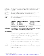
Страница 102: ...re continuing further Note that the 1041 injector is equipped with Electronic Flow Control as standard 1041 Injector Method The 1041 injector method component on the 3800 keyboard contains one screen...

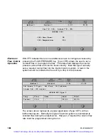
Страница 103: ...0 00 The screen above represents a typical application of type 3 EFC with an isothermal injector Normally this type of injection system is maintained at constant flow during the analytical run However...

Страница 104: ...jector Injector temperature 250 C Column temperature 50 C initial ramp to 250 C at 20 C minute and hold for 5 minutes Injection Volume 1 L Observe the eluting peaks for symmetry separation and elution...

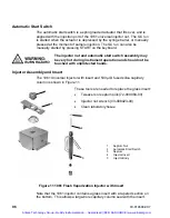
Страница 105: ...be touched with unprotected hands Injector Assembly and Insert The 1061 Universal Injector with insert and 530 ID fused silica capillary column is shown in Figure 11 Figure 11 1061 Flash Vaporization...

Страница 106: ...older then prepare column end and complete column connections to both the injector and detector fittings as detailed in the following paragraphs Preparing Column Ends To ensure a leak free connection...

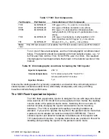
Страница 107: ...raphite ferrule urn past finger tight If a different size of column is used more tightening may be required New polyimide graphite ferrule to turn past finger tight May require retightening after firs...

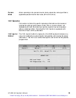
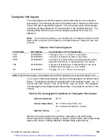
Страница 108: ...adjust the carrier gas flow to applicable packed column flow rates 20 to 50 mL min 1061 Operation This section contains the specific operating information and procedures required for optimum performan...

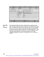
Страница 109: ...a required carrier flow into the injector column system A leak in the system would be indicated to the user by a drop in inlet pressure ACTIVE METHOD EDIT METHOD CTRL RUN TIME END TIME Method 1 Metho...

Страница 110: ...0 ng L of n pentadecane in iso octane TSD 82 005048 04 2 00 ng L of azobenzene methyl parathion 4 00 ng L malathion and 4 00 g L C17 in iso octane FID 82 005048 07 30 ng L of C14 C15 and C16 in iso oc...

Страница 111: ...A multi position valve oven which can accommodate up to six standard valves with 4 10 ports or one 12 port or larger valve including a Stream Selector Valve and four standard valves This valve oven is...

Страница 112: ...s are switched The following is an example of a type 4 EFC method used with a 3800 equipped with a gas sampling valve and a largebore 0 53 mm ID capillary column There are two separate type 4 method s...

Страница 113: ...is set about twice the required column flow rate For example if the desired column flow rate is 15 mL min set the total flow rate to 30 mL min When a valve switch is programmed the total flow should...

Страница 114: ...rs are mounted on the top of the 3800 above the left side of the column oven The position of the detector however is determined by the location of the detector s electrometer in the electronics cabine...

Страница 115: ...up gas you will be using with your FID 4 Install a chromatographic column in the GC refer to the 3800 Getting Started manual If the analytical column is not pre conditioned use a no hole ferrule in th...

Страница 116: ...rify that the flame is lit by monitoring the FID signal in the status region of the FID display Initially the signal will read a very high value but should then stabilize Typically the signal will be...

Страница 117: ...0 Actual C 300 Signal mV 5 15 FRONT FID Page 1 of 2 Oven Power ON Temperature C 300 Electronics ON Range 12 IGNITE AUTOZERO ADJUSTMENTS The IGNITE softkey applies power to the FID ignitor filament for...

Страница 118: ...od 1 Method 1 0 00 20 00 Make up Flow ml min 25 H2 Flow ml min 30 Air Flow ml min 300 FRONT FID ADJUSTMENTS Page 2 of 2 Make up Flow ml min 25 H2 Flow ml min 30 Air Flow ml min 300 Installation Disass...

Страница 119: ...gas supplies to the detector at the pneumatics panel These are the make up hydrogen and air supplies 3 Disconnect the signal and ignitor cables from their probes on the detector tower 1 Signal Cable 2...

Страница 120: ...d from the base Reassemble the FID Refer to Figure 13 to reassemble the FID detector To reassemble the FID proceed as follows 1 If you removed the detector oven from the plenum restore the oven to its...

Страница 121: ...lator into the detector tower then insert the collector tube into the tower The collector tube must not touch the ignitor coil 9 Insert the signal probe into the upper arm of the detector tower The pr...

Страница 122: ...ard in the detector bay Slide the PC board straight out of the guide slots in the cabinet If possible do not touch the edge connectors Place the PC board in a clean anti static bag 5 To install the PC...

Страница 123: ...ed heated zones The TSD will be listed as Zone 4 5 or 6 and its location Front Middle or Rear should appear in the Location column Check that the location corresponds with the physical location of the...

Страница 124: ...obe 1 Check the position of the TSD bead in the detector tower The TSD bead must NOT make contact with the TSD collector screen The bead should be located in the center of the collector with the colle...

Страница 125: ...reached its ignition point Allow the bead current to remain at this setting for a minimum of 12 hours preferably overnight This completes the initial conditioning of the TSD bead probe Now optimizati...

Страница 126: ...N 6 50 11 NO ON AUTOZERO ADJUSTMENTS The following pages are accessed by pressing the Adjustments softkey ACTIVE METHOD EDIT METHOD CTRL RUN TIME END TIME Method 1 Method 1 0 00 20 00 Set C 300 Actual...

Страница 127: ...from bead to bead Consequently for each new bead it is useful to chromatograph the detector test sample at several values of hydrogen flow from 4 to 5 5 mL min to determine the best hydrogen flow for...

Страница 128: ...s for a minimum of 24 hours at 40 C below the maximum temperature of the column packing liquid phase Since the TSD detects compounds containing nitrogen or phosphorus column packing materials containi...

Страница 129: ...on You can minimize the effect of chlorinated solvents on the bead by turning off bead current during the time that the solvent elutes using the time programming table of the detector method The total...

Страница 130: ...ng parts replacement or installation of another detector Disassembly re assembly instructions are detailed below for both the TSD and the detector oven TSD Disassembly The TSD is mounted on the ion de...

Страница 131: ...al Cable 2 Signal Probe 3 Bead Supply Cable 4 Bead Probe 5 Ceramic Bead 6 Collector 7 Ceramic Insulators 8 TSD Tower 9 Flame Tip 10 Aluminum Crunch Washer 11 Detector Base 12 Column Ferrule 13 Column...

Страница 132: ...ithdrawn from electrical contacts in tower 9 Carefully remove the flame tip assembly from the detector base 10 Remove and discard the aluminum seal washer from detector base In some cases this washer...

Страница 133: ...d probe by tightening knurled nut 9 Insert lower insulator with shoulder down into detector tower then insert collector tube with grid down Make sure the punch mark on the top edge of the collector is...

Страница 134: ...move the TSD PC Board proceed as follows CAUTION Turn the GC power OFF when removing or installing PC Boards 1 Collector with Screen Bottom 2 Ceramic Bead with Heater Coil 3 Flame Tip 4 Bead Probe 5 S...

Страница 135: ...s mounted directly above the column oven on the 3800 GC The TCD PC Board is installed in the electronics cabinet on the left side of the instrument TCD operating parameters are set at the 3800 keyboar...

Страница 136: ...limit 1 Press the Detector key and select the TCD by location Press the Adjustments softkey and select the carrier gas setting If you are using helium or hydrogen as carrier gas select the He setting...

Страница 137: ...N2 in the detector cells the filament protection feature is disabled when you use nitrogen or argon as the carrier gas Set the Filament Temperature Limit to 390 C or 490 C according to the highest fil...

Страница 138: ...rease in the detector noise WARNING FIRE HAZARD If hydrogen is used as a carrier gas vent the hydrogen from the TCD to a safe place Hydrogen is very flammable Before Operating the TCD Do not operate t...

Страница 139: ...ating the filaments 3 Allow system to equilibrate 10 to 15 minutes 4 Monitor the filament current through the detector status display Initially the current is greater than the final operating current...

Страница 140: ...DJUSTMENTS The AUTOZERO softkey applies an immediate zeroing of the detector signal Page 2 allows time programming events such as range changes ACTIVE METHOD EDIT METHOD CTRL RUN TIME END TIME Method...

Страница 141: ...a range of 0 05 mV yields about the same output signal as a filament current of 300 mA and a range of 0 5 mV At the lower current the detector noise is lower the stability is higher and the filament...

Страница 142: ...rate the TCD with the lowest filament and detector temperatures appropriate If possible avoid operating the TCD with a filament temperature greater than 390 C To operate the TCD with filament temperat...

Страница 143: ...K PW Partial pressure of H2O at ambient temperature in torr PA Ambient pressure in torr Note The 1 PW PA expression applies only if using a bubble flowmeter EXAMPLE 2 Known Concentration of Sample in...

Страница 144: ...eversed during a chromatographic run Set a time programmed polarity reversal in the detector method section Adjust TCD Carrier Gas Flow Rates All 3800 GCs equipped with TCDs are factory tested at the...

Страница 145: ...binet If possible do not touch the edge connectors Place the PC board in a clean anti static bag 5 Place the PC board in an anti static bag and set aside To install the TCD PC Board proceed as follows...

Страница 146: ...ngs on the GC 2 Check the gas supply pressures The GC is set for N2 He or Ar CH4 at 80 psig Reset the gas flows if you intend to use different supply pressures Refer to the 3800 Pre Installation Instr...

Страница 147: ...time programming events such as range and Autozero ACTIVE METHOD EDIT METHOD CTRL RUN TIME END TIME Method 1 Method 1 0 00 20 00 Set C 300 Actual C 300 Signal mV 2 15 FRONT ECD Page 2 of 2 Time Range...

Страница 148: ...avoidable when using nitrogen as the carrier gas In such instances the baseline signal may be too high Select the N2HIGH setting in these situations In general the baseline signal should never exceed...

Страница 149: ...to come to temperature and equilibrate for several hours or preferably overnight From the ECD screen press the soft key labeled Adjustments to display the Cell Current control Press the Clear Autozer...

Страница 150: ...columns and septa before you use them with the ECD Column Conditioning NEVER condition a column while it is connected to the ECD detector Instead remove the column from the detector cap the ECD colum...

Страница 151: ...with material bleeding from the column The higher the temperature of the foil the greater the rate of migration of the 63 Ni into the backing material Rapid migration of the 63 Ni reduces the electron...

Страница 152: ...16 inch OD exit tube of the ECD cell Attach the other end of the flow tube assembly to a flowmeter To prevent cross contamination between detectors use the flow tube only with the ECD and store the a...

Страница 153: ...and pulser probe 4 Insert the installation tool into the detector tower assembly located over the detector cell Loosen the hex nut until the cell turns freely 5 Remove the two 8 32 x 3 inch tower mou...

Страница 154: ...lectrode contacts WARNING NON SERVICEABLE ASSEMBLY Do not attempt to remove the cell assembly which is fixed inside the tower 4 Check to see whether the detector tower base and detector cell fittings...

Страница 155: ...ncounter any resistance during the insertion of the probes check that the probes are being installed in the correct positions 10 Install the insulated detector tower cap The label shown in Figure 21 i...

Страница 156: ...e ECD PC Board is a slide in module To remove the ECD PC Board proceed as follows WARNING SHOCK HAZARD Dangerous voltages exposed Turn the GC power OFF when you remove or install PC boards Failure to...

Страница 157: ...ed with a separate manual P N 03 914649 00 All 3800 GCs equipped with a PFPD will be supplied with this manual which containscomplete setup and operating information for the PFPD Artisan Technology Gr...

Страница 158: ...800 detectors FID Test Mix Column Non polar e g 1 film thickness 15m x 0 25 mm CP Sil 5 CB Carrier Nitrogen 5 mL minute Injection 1079 200 C 1 L splitless Temperature Program 80 hold 1 minute 20 minut...

Страница 159: ...m x 0 25 mm CP Sil 5 CB Carrier Nitrogen 5 mL minute Injection 1079 200 C 1 L splitless Temperature Program 80 hold 1 minute 20 minute to 200 hold 1 minute Detector 300 C Range 12 Artisan Technology G...

Страница 160: ...CB Carrier Helium 5 mL minute Injection 1079 200 C 1 L splitless Temperature Program 80 hold 1 minute 20 minute to 200 hold 1 minute Detector 220 C Range 0 05 Filament Temperature 270 20 Filament cur...

Страница 161: ...CP Sil 5 CB Carrier Nitrogen 5 mL minute Injection 1079 200 C 1 L splitless Temperature Program 80 hold 1 minute 20 minute to 200 hold 1 minute Detector 300 C Range 1 Capillary current setting Artisan...

Страница 162: ...C 1 L splitless of a 1 30 dilution of FPD test mix in iso octane Temperature Program 80 hold 1 minute 20 minute to 200 hold 1 minute Detector 300 C Range 10 Air1 17 mL min Hydrogen 14 mL min Air2 10...

Страница 163: ...splitless of a 1 30 dilution of FPD test mix in iso octane Temperature Program 80 hold 1 minute 20 minute to 200 hold 1 minute Detector 300 C Range 10 Air1 17 mL min Hydrogen 14 mL min Air2 10 mL min...

Страница 164: ...nalog data to integrators and data systems Ethernet Communications Ethernet refers to the type of hardware connection used to transfer digital data between the 3800 GC and the data system to which it...

Страница 165: ...Connection with the Star Workstation may take as long as one minute If after one minute the 3800 has not connected to the workstation power the GC off and on to repeat the sequence 10Base2 Ethernet Ca...

Страница 166: ...5 shows schematically how this cabling would look when viewed from above Keyboard 3800 GC 10Base2 Ethernet Cable BNC Terminator BNC Terminator BNC Tee BNC Tee 3800 GC Comm Board Star WS Ethernet Comm...

Страница 167: ...BNC Tee 3800 GC Comm Board Star Workstation Computer Star WS Ethernet Comm Board Disconnected here Unacceptable Disconnections 10Base2 Ethernet Cable BNC Terminator BNC Tee Disconnected here Star Wor...

Страница 168: ...GC 10Base2 Ethernet Cable BNC Terminator BNC Tee BNC Tee Keyboard 10Base2 Ethernet Cable BNC Terminator BNC Tee 3800 GC BNC Tee 3800 GC 3800 GC 3800 GC 10Base2 Ethernet Cable 10Base2 Ethernet Cable S...

Страница 169: ...he top left cover This connector contains all three analog channels plus status signals for Ready In to the GC and Start Out from the GC The individual analog ports can be assigned to any installed de...

Страница 170: ...hich the analog output will be connected such as integrators and analog data systems are equipped with attenuation control The signal sent from the GC in this case should not be attenuated The 3800 ha...

Страница 171: ...ed to the 4400 Integrator Channel A Similarly Analog Output Port B is connected to the 4400 Integrator Channel B Analog Output Port C is not connected Three channel analog cable with status connector...

Страница 172: ...tion the Manual Injection mode must be selected in Automation Select Edit and then Remote Control must be enabled in the Instrument Menu section of the 3800 keyboard 3800 local automation consists of...

Страница 173: ...g one of the seven available valve drivers on the 3800 The two gas sampling valve states are identified as Fill and Inject Fill refers to the state when the sample is purging through the sample loop o...

Страница 174: ...n Manual Injection is the default when the 3800 is first powered on In the Manual Injection mode local automation is inactive The user can program the 3800 from the keyboard or download methods includ...

Страница 175: ...will be terminated Automation Methods Local 3800 automation methods differ depending on whether or not an addressable device is detected Addressable devices are connected to one of the serial interfac...

Страница 176: ...d then select Single Method as the automation choice Press the 3800 Start key to start automation Note that if the method specified in Single Method Automation is different from the currently active 3...

Страница 177: ...f times the method specified in that line of the table should be run The allowable entries are 1 999 Method Sequence automation page 2 of 2 ACTIVE METHOD EDIT METHOD CTRL RUN TIME END TIME Method 1 Me...

Страница 178: ...t 8400 vial to be sampled and final sample is the final 8400 vial to be sampled The automation method will sample all vials that are present in the 8400 carrousel in this sample range As an example if...

Страница 179: ...e automation table can consist of up to 25 lines Lines are added by pressing the New Line key on the 3800 keyboard Note that for any given line the final sample must be greater than the initial sample...

Страница 180: ...des Standard On Column Standard Split Splitless Volatile Neat Viscous and User Defined These modes are explained in detail in the 8400 Operator s manual The sampling mode is selected using the increme...

Страница 181: ...e is being run and sample vial refers to the specific 8400 vial being sampled 0 99 Note that table line number is blank if Single Method automation is active Running Priority Sample The priority sampl...

Страница 182: ...hether the automation status is ready running or suspended Injection number refers to the number of injections of the specific method Table line number indicates the line number if a method sequence i...

Страница 183: ...uipment Have surplus equipment taking up shelf space We ll give it a new home Learn more Visit us at artisantg com for more info on price quotes drivers technical specifications manuals and documentat...

Отзывы: