126
03-914648-00:7
1
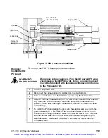
Turn the GC power OFF.
2
Disconnect the signal and ignitor cables from detector.
3
Remove the left side panel from the GC by removing the 8 -32 screws.
4
Remove the 8 -32 screw securing the TSD electrometer board in the
detector bay. Slide the PC board straight out of the guide slots in the
cabinet. If possible, do not touch the edge connectors. Place the PC board
in a clean anti-static bag.
5
To install the PC board, align the groove in the electrometer cover with the
guide rail at the top of the detector bay and slide the electrometer into the
opening until the edge connector seats in the socket. Never force the board
into the cabinet. Make sure that all cables are out of the way before you
insert the board. Reconnect the cables to the detector. Check that the
connectors mate.
Thermal Conductivity Detector
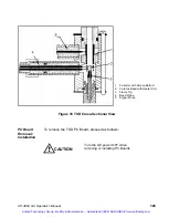
The Thermal Conductivity Detector (TCD) is mounted directly above the
column oven on the 3800 GC. The TCD PC Board is installed in the
electronics cabinet on the left side of the instrument.
TCD operating parameters are set at the 3800 keyboard: These include
carrier gas type, detector temperature, range, temperature limit, and filament
temperature. Carrier gas flow is set and controlled at the pneumatics panel,
and in the Adjustments section of the method if Detector EFC is installed.
Initial Set-Up
To set up the TCD, proceed as follows. Note that the TCD is a two channel
detector and requires both a sample flow of carrier gas and a reference flow
of the same gas. Either channel can be used as the sample stream but there
must always be a reference stream.
1
Connect the gas lines to the appropriate bulkhead fittings on the GC.
2
Check the gas supply pressures. Flow controllers with turn dials are
calibrated for Helium at 80 psig. Recalibrate the flow controllers if you use a
different supply pressure or carrier gas.
Artisan Technology Group - Quality Instrumentation ... Guaranteed | (888) 88-SOURCE | www.artisantg.com

