TS
−
I Special servo drive for hybrid electro-hydraulic system of injection molding machine User Manual
Chapter 3 Digital actuator button, display and motor learning
37
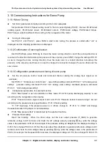
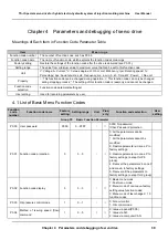
3.10 Commissioning Instructions for Servo Pump
3.10.1 Motor Tuning
Set motor parameters correctly according to the motor nameplate
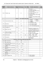
Set parameter P0.04=0 “Speed setting mode” to “Set via panel digitally (P0.05)”, then set P9.02=rated
rotating speed, P9.03=rated power, P9.04=rated current, P9.05=rated voltage, P9.06=rated torque,
P9.07=torque current coefficient Kt according to the nameplate of the motor.
Tuning of initial angle
Set P9.23=1 and P9.24=1, press RUN to start motor tuning, the process is ended after “-At-“ is
displayed and the stopping parameters are displayed.
3.10.2 Confirmation of running direction
Set P0.05=20rpm, press RUN key to check the motor running direction, and if the running direction is
reverse to the direction that builds up the pressure of the oil pump, press STOP, change the setting of P0.07
so as to change the motor running direction, thus the motor runs in a correct direction to build up the
pressure in the oil pump, and there is no need to change the connection between the servo driver and the
servo motor.
3.10.3 Configuration parameters and tuning of servo pump
Set the oil pressure control mode and command channel (taking the analog input signal as an
example)
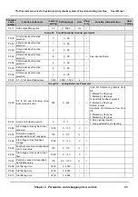
Set P0.03=1
“
Oil pressure control mode
”
, speed (flow) setting command P0.04=1
“
AI3 analog value
setting
”
, pressure setting command P1.03=1 “AI1 analog value setting“, feedback pressure command
P1.04=1 “AI2 analog value setting”.
Configuration parameters for selected machine
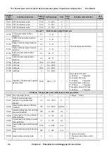
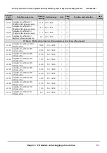
P0.13 ”Max speed” is set via calculation of flow meter, P1.00 “Oil pump discharging capacity” is set
according to the nameplate on the oil pump.
P1.01 “Pressure sensor signal output mode” and P1.02 “Pressure sensor measure range” are set
according to the pressure sensor specifications. P1.01=0 factory setting
“0
~
10V” input type, if the pressure sensor is 4
~
20mA, change to P1.01=4 “4
~
20mA” and change
the selection switch S3 jumper to I terminal status.
P1.06 “Max pressure limit” is determined by the selected machine.
Pressure flow marking
Direct line marking: When the driver stops, set the max output pressure (P_MAX) to generate
reference voltage to AI1 terminal, and check the AI1 voltage value by pressing >> key, write the voltage
value in the parameter of P6.02, for example: If the pressure setting is 140kgf/cm2, the displayed voltage is
9.45V, then change P6.02 to 9.45; Set the max output flow (Q_MAX) to generate reference voltage to AI3
terminal, and check the AI2 voltage value by pressing >> key, write the voltage value in the parameter of
P6.06, for example: Set the speed 99% test value, the displayed voltage is 9.15V, then change P6.06 to 9.15.
Содержание TS-I Series
Страница 1: ...User Manual TS I series servo drive is introdution V T ...
Страница 2: ......


