


Hydraulics installation
Installation instructions geoTHERM 0020051574_04
37
5
42a
1
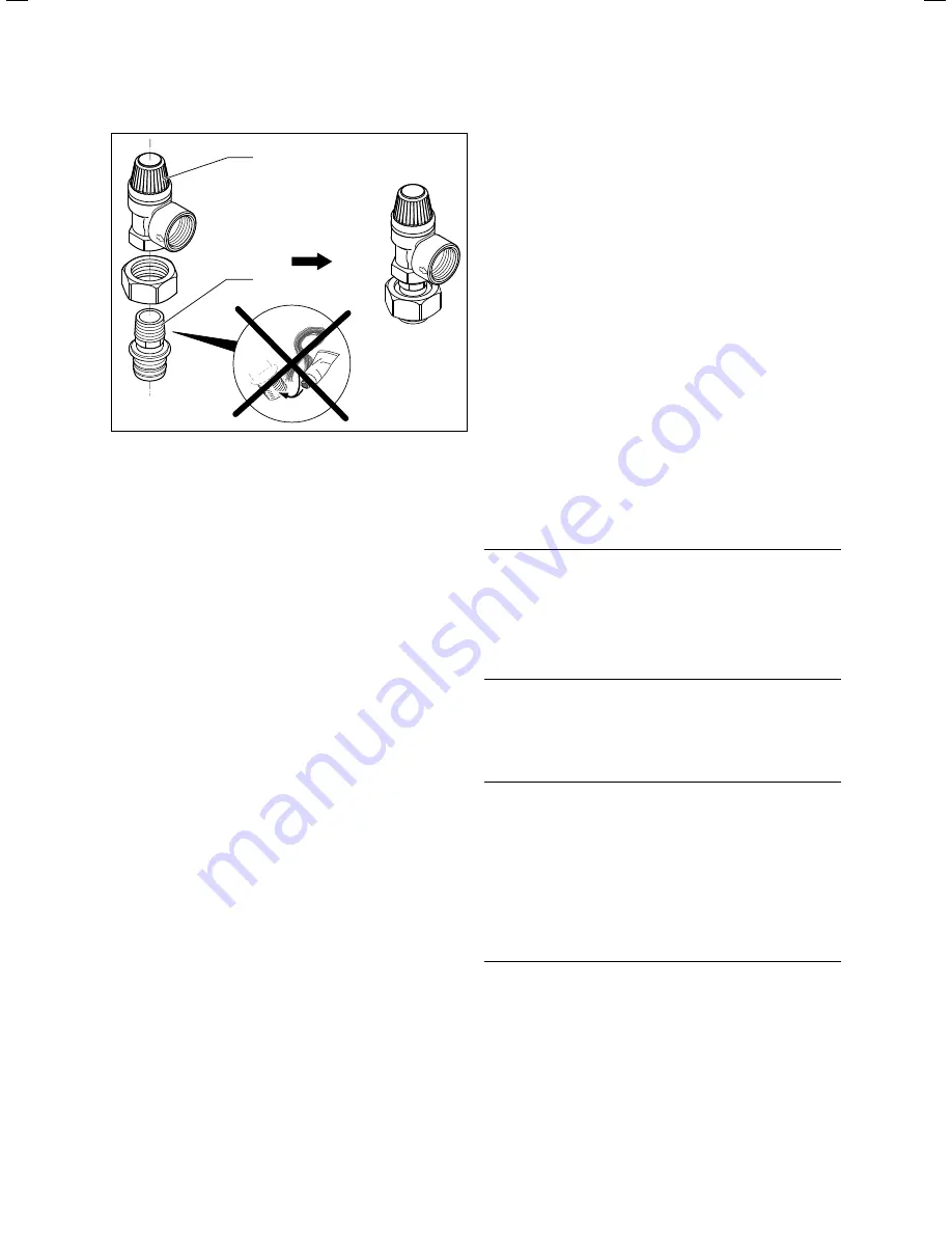
5.11 Fitting the expansion relief valve
>
Seal the outside thread of the upper connecting piece (
1
)
using a sealant, e.g. Teflon tape.
>
Fit the connecting piece to the 3 bar expansion relief
valve (
42a
) that is attached to the heat pump.
>
Fit the upper connecting piece with the expansion relief
valve to the brine expansion tank.
>
Use the bracket to fix the brine expansion tank.
>
Connect a hose/pipeline to the expansion relief valve.
Allow the end of the hose to be open in the brine collect-
ing tank.
>
Install the brine expansion tank (
65
) (
¬
Fig.
5.9
) without
pressure on the expansion relief valve (
42a
).
The brine collecting tank must not be completely closed
because, otherwise, it cannot be guaranteed that the
expansion relief valve will work.
5.10
Connecting the heat pump to the well water
circuit (VWW only)
In most cases, if well water is used as the heat source, the
well system must be run using suction and injection wells.
The ends of the pipelines of the suction and injection wells
must lie deep enough below the well water surface to pre-
vent the water from taking in oxygen from the air. This oxy-
gen leads to the coagulation of iron and manganese that is
dissolved in the water and this, in turn, may lead to deposits
in the injection well and the heat exchanger in the heat
pump.
>
In the suction well, install the well pump (immersion
pump) that must be installed on-site. Follow the well
pump installation and assembly instructions in this
respect.
The electrical connection for the well pump is described in
(
¬
Ch.
7.3.4
).
>
Fit the well water pipelines along with all the associated
components in accordance with the applicable technical
guidelines.
b
Caution!
Risk of damage caused by solid particles.
Solid particles (e. g. sand) in the well water
may clog the evaporator.
>
In the inflow to the heat pump,
install a flushable fine filter
(mesh width 100 - 120
m
m).
>
Connect the well water pipelines to the heat pump (
3
)
and (
4
) (
¬
Fig.
5.8
).
>
Insulate all pipelines using vapour diffusion-tight insula-
tion.
b
Caution!
Risk of damage caused by negative pres-
sure.
Negative pressure in the well water pipe-
lines may cause damage to the flexible
hoses within the heat pump.
>
Ensure that there cannot be any nega-
tive pressure in the pipelines when oper-
ating and after switching off the well
pump.
Содержание geoTHERM SERIES
Страница 1: ...Installation instructions For the heating engineer GB Installation instructions geoTHERM Heat pump...
Страница 21: ...Installation Installation instructions geoTHERM 0020051574_04 21 4 4 6 Permitted modes of transport...
Страница 132: ...0020051574_04 GB 082014 Subject to change Manufacturer Supplier...