


Appendix
Installation instructions geoTHERM 0020051574_04
125
17
Pressure
sensors
Pressure sensor
Heating circuit
Pressure sensor
Brine circuit
Low-pressure
sensor
High-pressure
sensor
Temperature sensors
AMU
Fuse
T4A/250 V
Fuse
T4A/250 V
Phase monitoringPhase monitoring
brown
grey
black
L1
L2
L3
brown
grey
black
L3
L2
L1
PE
Compressor
black
black
1
L
N
1
2
SCH
21
7
LN
8
21
AS
B
L
N
2
L
N
3
L
N
4
LN
6
L
N
5
12
VF2
12
RF1
12
VF1
-
+
BUS
12
EV
U
12
1xZP
DCF
O
T
AF
DCF
/AF
N
L
ZH
N
On
Of
f
LP
/UV 1
N
L
SK2
-P
N
L
SK2
-P
N
L
HK2
-P
N
On
Of
f
HK2
12
SP
blue
brown
yellow-green
blue
brown
yellow-green
blue
brown
yellow-green
brown
yellow-green
orange
orange
red
black
blue
grey
white
white
L1
L2
L3
Co
n
tro
l
c
o
nt
act
or
Brine pump
T1
T2
T3
A1
A2
L1
L2
L3
Pr
ot
ect
or
c
o
nt
act
or
Brine pump
T1
T2
T3
A1
A2
A2
L1
L2
L3
Ext
ernal aux.
he
at
er
c
o
nt
act
or
T1
T2
T3
A1
brown
grey
black
brown
grey
black
black
A2
L1
L2
L3
Pr
ot
ect
or
c
o
nt
act
or
C
ompr
e
s
s
or
T1
T2
T3
A1
A2
PE
yellow-green
orange
black
orange
blue
M1
T2
M2
T1
brown
black
grey
blue yellow-green black
brown
grey
black
1 2 3 4 5 6
brown
black
yellow-green
grey black black
6 5 4 3 2 1
L2
L3
WSK
L1
PE
WSK
L2
WSK
L1
PE
WSK
L3
C
onnection
Brine pump
1
2
3
4
5
6
N
PE
L
L1
L2
L3
C
onnection
Brine pump
L1
PE
L
N
L2
L3
yellow-green
blue
black
grey
brown
1
2
3
4
5
6
L3
L2
L1
PE
TOP-S40/10 3~
vrnetDIALOG
L
N
PE
2
1
N
PE
L
N
PE
SS
L
N
PE
L3
N
PE
L2
L1
L3
N
L3
L2
L1
N
PE
L3
L2
L1
N
PE
Ext
ernal auxiliary he
at
er
(t
o be fit
ted on-sit
e
)
he
ating cir
cuit
pump (
to be
fit
ted on-sit
e
)
Primary
mains supply
3
00 x 400 V PEN
Brine
swit
ch
(to
b
e
fit
ted
on-sit
e
)
blue
blue
blue
blue
black
grey
brown
grey
black
orange
orange
black
black
brown
grey
black
brown
grey
black
black
black
brown
grey
black
black
orange
brown
black
grey
brown
yellow-green
blue
brown
blue
grey
black
black
grey
brown
black
brown
blue
yellow-green
orange
orange
M
Brine mixing
v
alv
e (
to be
fit
ted on-sit
e
)
p
p
High-pressure
switch
Low-pressure
switch
Start-up current limiter
W
L3
L2
L1
V
U
X2
X1
X3
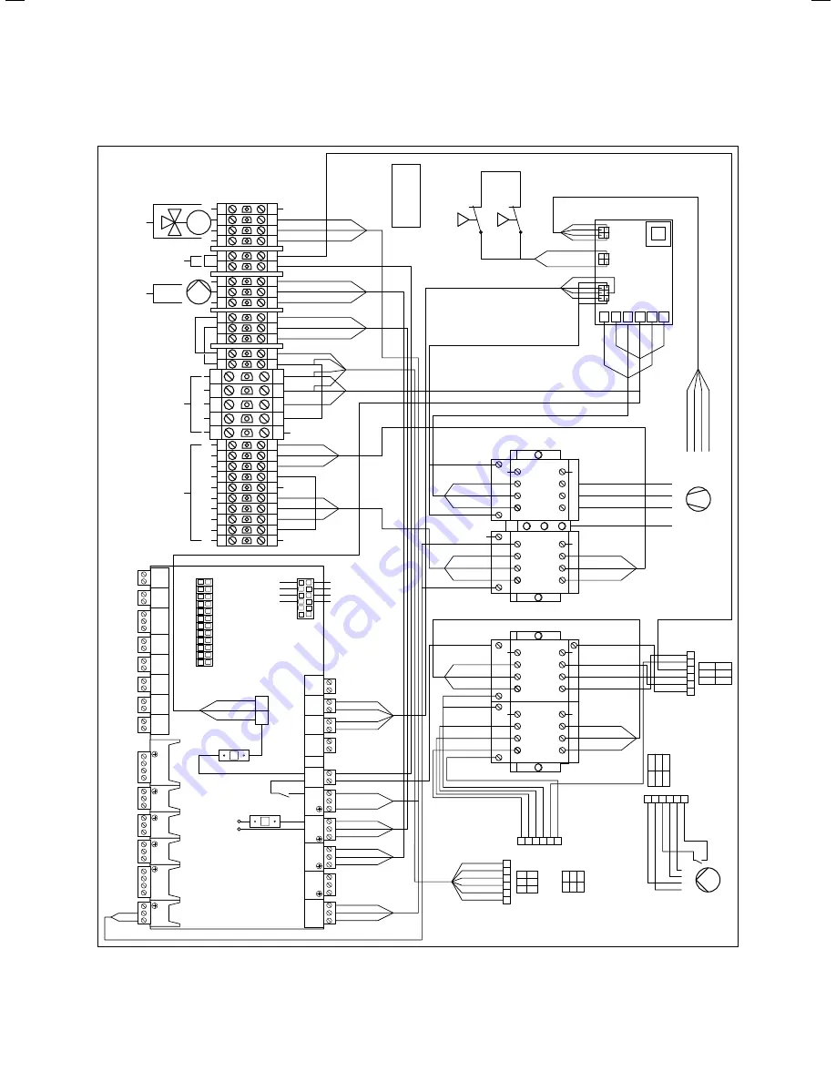
17.4 Appendix,
Electrical circuit diagram VWS 380/2 - VWS
460/2
Содержание geoTHERM SERIES
Страница 1: ...Installation instructions For the heating engineer GB Installation instructions geoTHERM Heat pump...
Страница 21: ...Installation Installation instructions geoTHERM 0020051574_04 21 4 4 6 Permitted modes of transport...
Страница 132: ...0020051574_04 GB 082014 Subject to change Manufacturer Supplier...