Instructions and settings
48
Ver.2 01.11.2002
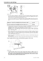
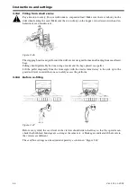
5 Clamp the top rod to eliminate any lateral play. If necessary, use the enclosed spacers between
the rod and the top rod mount. Lock the bolt with the locking nut on the outside.
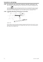
Figure 3.57
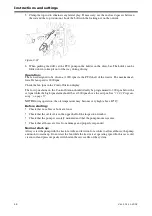
6 When parking the drill, set the PTO pump in the holder on the draw-bar. The holder can be
folded down to keep it out of the way during driving.
Operation:
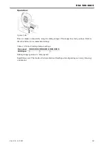
The fan is designed to be driven at 1000 rpm via the PTO shaft of the tractor. The maximum al-
lowable fan speed is 6000 rpm.
Check the fan rpm in the Control Station display.
The low rpm alarm on the Control Station should ideally be programmed to 300 rpm below the
set rpm while the high rpm alarm should be set 300 rpm above the set rpm. See ”
.
NOTE!
During operation, the oil temperature may become very high (above 80
o
C)!
Before starting:
!
Check that no cables or bolts are loose.
!
Check that the oil level is in the upper half of the inspection window.
!
Check that the pump is securely mounted and that the pump mount
is secure.
!
Check that all hoses are free from damage and properly suspended.
Normal start-up:
Always start the pump with the tractor at idle and let it run for a while to allow all hoses, the pump
and motor to warm up. Do not start the fan while the tractor is at operating speed. In this case cold,
viscous oil and pressure peaks will shorten the service life of the system.
Содержание RAPID RDA S Series
Страница 1: ...Ver 2 01 11 2002 900225 en Instructions Seed drill RAPID series RDA 500 800 S No 12 000 12 799...
Страница 2: ...2 Ver 2 01 11 2002...
Страница 4: ...4...
Страница 73: ...RDA 500 800 S Ver 2 01 11 2002 73...
Страница 75: ...RDA 500 800 S Ver 2 01 11 2002 75 Figure 5 4...
Страница 105: ...RDA 500 800 S Ver 2 01 11 2002 105...
Страница 106: ...Appendices 106 Ver 2 01 11 2002 7 3 Hydraulic diagram 7 3 1 Hydraulic diagram RDA 500 600 S Figure 7 1 428717...
Страница 108: ...Appendices 108 Ver 2 01 11 2002 7 3 2 Hydraulic diagram RDA 800 S Figure 7 2 428718...
Страница 110: ...Appendices 110 Ver 2 01 11 2002 7 3 3 Fenix fl kt standard Figure 7 3 A Hydraulic motor B Valve block C Tractor B A C...
Страница 121: ......


