V2 CITY1 Скачать руководство пользователя страница 7

E

N

G

L

IS

H

30

CONTROL PANEL

When power is on, the control unit checks that display correctly
operates by switching on all segments for 1.5 sec. 

8.8.8.8.

Firmware version, e.g. 

Pr 2.0

, will be viewed in the following 1.5

sec. Panel will be viewed upon completion of this test.

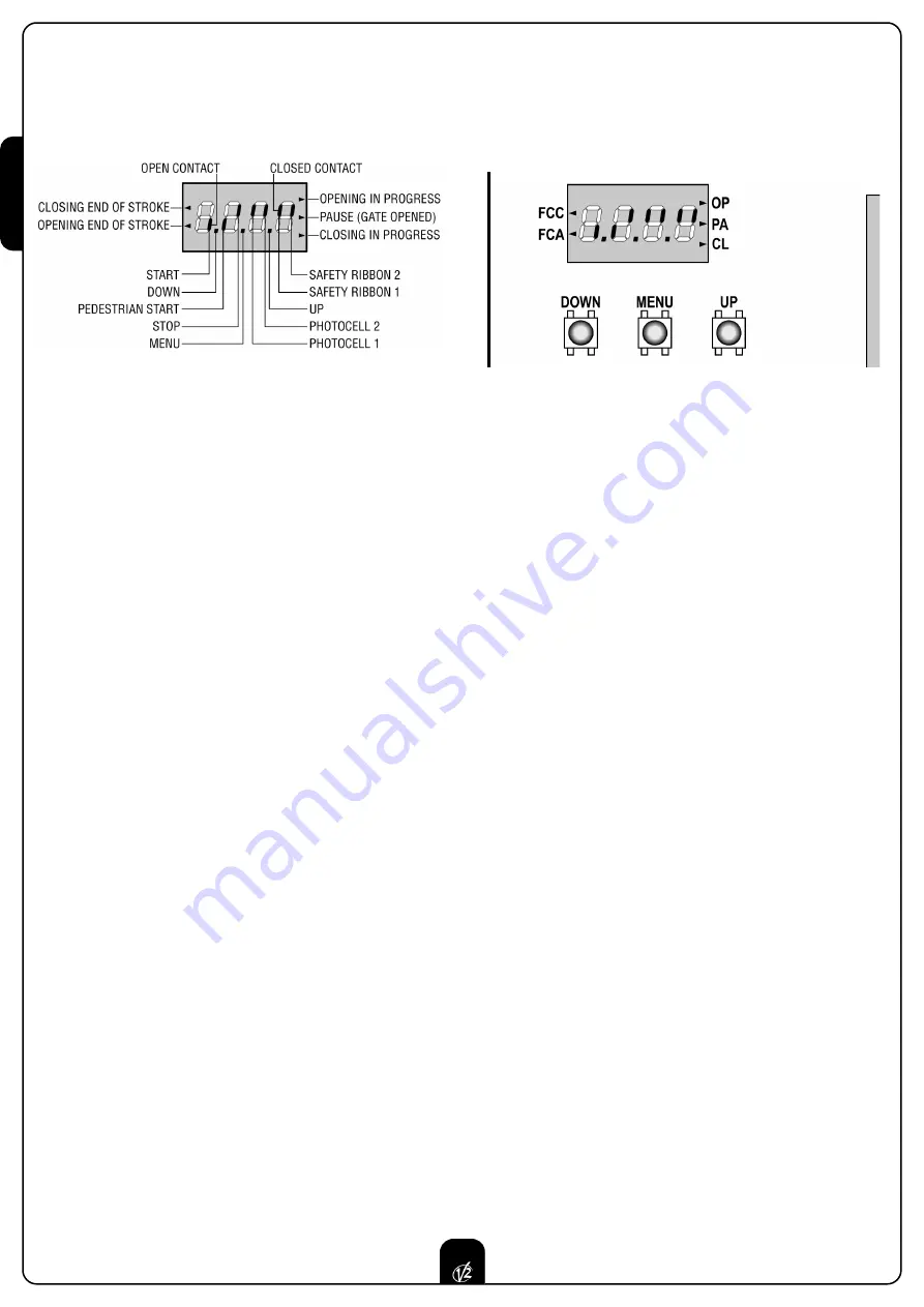
The control panel represents the physical status of the 
terminal board contacts and of the program mode keys: if the
upper vertical segment is on, the contact is closed; if the lower
vertical segment is on, the contact is open (the above picture
shows an instance where the inputs START, START P, FOTO 1,
FOTO 2,COSTA 1, COSTA 2 and STOP have all been correctly
connected).

Points being among display digits show the status of
programming push-buttons: as soon as a push-button is pressed,
its relevant point turns on. 

The arrows on the display left side show the status of the ends of
stroke. As for a one door-gate, arrows turn on when its end of
stroke shows that the gate is completely closed or 
completely open.

As for a two-door gate, arrows turn on when both the ends of
stroke show that both the doors are completely closed or 
completely open; the arrow will blink in case only one door 
reaches its end of stroke. 

WARNING:

these functions have not been activated in case of

ends of stroke being connected in series to the motor. 

The arrows on the display right side show the gate status:
• The highest arrow turns on when the gate is into its opening 

phase. If it blinks, it means that the opening has been 
caused by a safety device (border or obstacle detector).

• The central arrow shows that the gate is on pause. If it 

blinks, it means that the time countdown for the automatic 
closing has been activated. 

• The lowest arrow blinks when the gate is into its closing 

phase. If it blinks, it means that the closing has been 
caused by a safety device (border or obstacle detector).

USE OF DOWN MENU AND UP KEYS FOR 
PROGRAMMING 

Control unit time and function programming is made within a
special configuration menu, to which you can access and where
you can shift through 

DOWN, MENU

and 

UP

keys placed under

the display.

Hold down the MENU key until 

dEF

appears on display, to 

activate the programming mode while display views the panel.

Configuration menu consists of a list of configurable items; the
wording appearing on display will show the current selected item. 

By pressing DOWN, you will pass to the next item; by pressing UP,
you will return to the previous item.
By pressing MENU, you can view the current value of selected
item and possibly change it. 

The last menu item (

FinE

) allows storing the carried out 

changes and going back to the control unit normal operation.
You must exit from programming mode through this menu item
if you do not want to lose your configuration. 

WARNING:

in case no operation is carried out for more than one

minute, the control unit exits from the programming mode
without saving any of your setups and changes, which will get
lost.

By holding down the DOWN key, configuration menu items will
scroll fast, until item 

FinE

is viewed. Viceversa, by holding down

the UP key, items will scroll fast backwards until item 

dEF

is

viewed. In this way, you can quickly reach either the top or 
bottom of the list.

There are the following three kinds of menu items:
• Function menu
• Time menu
• Value menu

Function menu setup

Function menus allow selecting a function from among a group
of available options. When you enter into a function menu, the
current active option will be viewed; you can scroll all available
options through DOWN and UP keys. By pressing the MENU key,
you will activate the option viewed and you will return to the
configuration menu.

Содержание CITY1

Страница 1: ...IL n 170 1 EDIZ 04 03 2009 V2 S p A Corso Principi di Piemonte 65 67 12035 RACCONIGI CN ITALY tel 39 01 72 81 24 11 fax 39 01 72 84 050 info v2home com www v2home com CITY1 I...

Страница 2: ...Y RIBBONS 28 LOCK 28 END OF STROKE 28 ENCODER 28 STOP 28 ACTIVATION INPUTS 29 EXTERNAL AERIAL 29 PLUG IN RECEIVER 29 OPTIONAL MODULES 29 CONTROL PANEL 30 USE OF DOWN MENU AND UP KEYS FOR PROGRAMMING 3...

Страница 3: ...N 12453 allows We recommend to make use of an emergency button to be installed by the automation connected to the control unit STOP input so that the gate may be immediately stopped in case of danger...

Страница 4: ...d in case of disabled obstacle sensor is described WARNING In case it has not yet fitted a start capacitor for each motor is required connect the start capacitor for motor 1 between terminals 27 and 2...

Страница 5: ...good closing of doors Make use of a 12V lock Connect lock cables to terminals 20 and 21 of the control unit END OF STROKE CITY1 control unit supports the two following kinds of end of stroke end of s...

Страница 6: ...f device controlling the first input between terminals 3 and 6 of the control unit Connect cables of device controlling the second input between terminals 4 and 6 of the control unit The first input f...

Страница 7: ...nto its closing phase If it blinks it means that the closing has been caused by a safety device border or obstacle detector USE OF DOWN MENU AND UP KEYS FOR PROGRAMMING Control unit time and function...

Страница 8: ...the doors will be activated in closing direction until the stop end or the closing end of stroke is reached Be sure that the leaves do not overlap In case NEITHER the ends of stroke NOR the obstacle s...

Страница 9: ...ning phase before the relevant time expires WARNING if motor 2 is not connected this time must be set to zero in this circumstance the control unit will not consider all configurations of motor 2 and...

Страница 10: ...mmand it will use this time to close the gate Max allowed time to be setup is t CH1 To avoid that the door does not close completely we recommend to setup a longer time than t APP opening time Leaf 2...

Страница 11: ...motors to help the electric lock release The control unit controls the motors in reduced power in closing direction for the setup time The backlash precedes the electric lock release It is possible t...

Страница 12: ...down function in order to measure both opening and closing times and to enable it again once the setup has been carried out The control unit will automatically consider the working time delay caused b...

Страница 13: ...the step by step operation logic Select option APEr to set up the always open operation logic Start command during the pause This menu allows fixing the control unit conduct in case it receives a Sta...

Страница 14: ...n is disabled by setting the value to zero no will be displayed the gate can be closed through the start command only in this case St PA menu setup will be ignored If the control unit receives a Stop...

Страница 15: ...ns associated to the command of STOP no The input STOP is not available ProS The input STOP stops the gate pressing the command START the gate continues the motion invE The command STOP stops the gate...

Страница 16: ...In some installations it may occur that the gate door passes before the photocells so breaking their beam In this case the gate cannot complete its closing cycle Through this function photocells can...

Страница 17: ...eached its position of complete opening or closing no End of stroke inputs are disabled Si End of stroke inputs are enabled Motor Release on Mechanical Stop When the gate halts against the mechanical...

Страница 18: ...exactly to the starting position it is possible to set an anti skid time that is added to the time calculated by the control unit in order to recover the inertia WARNING If function ASM is disabled t...

Страница 19: ...d the learning cycle starts WARNING The procedure of the operation time automatic learning can be starter only if the Start inputs are set up on the STANDARD mode StAn End of Programming This menu all...

Страница 20: ...cles after which the next service will be requested In case no new value is setup that is to say that the counter value is left at zero the signalling function for the service request will be disabled...

Страница 21: ...0 no Pre flashing disabled it corresponds to 0 Pot1 30 100 Motor 1 power 60 60 Pot2 30 100 Motor 2 power 60 SPUn no Si Start off no Si t P So 0 5 3 0 Slowed down starting time 1 5 no no Slowed down s...

Страница 22: ...no no no Function disabled F ShA FOTO2 disabling higher time i ShA FOTO2 disabling lower time CoS1 no Si Border 1 input fixed border no no CoS2 no Si Border 2 input mobile border no no FC En no Si En...

Страница 23: ...ing phase N C contact 16 Common 17 18 Power output 24 VAC for photocells and other accessories 18 19 Photocell TX power supply for functional test 20 21 Electric lock 12VAC 22 23 Flashing light 230VAC...

Страница 24: ...K 2 x 1 5 mm2 PG9 For cables with external from 5 to 8 mm OTHER WIRINGS MULTIPOLAR n x 0 25 0 5 mm2 n depending on the number of wirings to be made PG9 For cables with external from 5 to 8 mm PG11 For...

Страница 25: ...sure that photocells are powered and working when you interrupt their beam you should hear the relay tripping Error 4 After few centimeters during the opening phase the gate stops and the display show...

Страница 26: ...V2 S p A Corso Principi di Piemonte 65 67 12035 RACCONIGI CN ITALY tel 39 01 72 81 24 11 fax 39 01 72 84 050 info v2home com www v2home com...

Отзывы: