V2 CITY1 Скачать руководство пользователя страница 5

E

N

G

L

IS

H

28

SAFETY RIBBONS

The control unit considers two kinds of safety ribbons, 
depending on the terminal to which they are connected:

Type 1 (fixed):

they are mounted on walls or on other fixed 

obstacles that are approached by the gate doors during the 
opening phase. When type 1 safety ribbons operate during 
the gate opening phase, the control unit will close the doors 
for 3 seconds, then it stands still; when type 1 safety 
ribbons operate during the gate closing phase, the control 
unit will stand still immediately. The direction of the gate at 
next command of START or PEDESTRIAN START depends 
upon the parameter STOP (it inverts or continues the 
motion). If the input STOP is disabled, the command makes 
the motion continue in the same direction.

Type 2 (mobile):

they are mounted to the door ends. 

When type 2 safety ribbons operate during the gate opening 
phase, the control unit will stand still immediately; when 
type 2 safety ribbons operate during the gate closing, the 
control unit will open the doors for 3 seconds, then it will 
stand still. The direction of the gate at next command of 
START or PEDESTRIAN START depends upon the parameter 
STOP (it inverts or continues the motion). If the input STOP 
is disabled, the command makes the motion continue in the 
same direction.

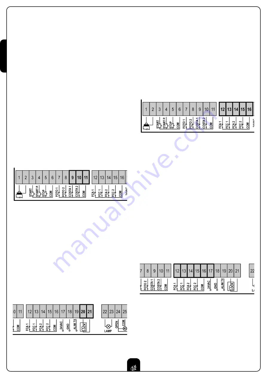
Connect type 1 safety ribbons cables between terminals 

9

and 

11

of the control unit.
Connect type 2 safety ribbons cables between terminals 

10

and

11

of the control unit.

In order to meet the requirements of the EN12978 rules, it is
necessary to install safety edges controlled by a control unit
continuously checking the proper working. If using control units
suited to the test by power outage, connect the power supply
cables of the control unit between terminals 19 and 18 of the
CITY1. Otherwise, connect them between terminals 17 and 18.

WARNING:

• Make use of safety ribbons having outputs with normally 

close contact. 

• Outputs of same kind safety ribbons must be connected in 

series.

LOCK

An electric lock can be assembled on the gate, to ensure a good
closing of doors. Make use of a 12V lock. 
Connect lock cables to terminals 

20

and 

21

of the control unit.

END OF STROKE

CITY1

control unit supports the two following kinds of end of

stroke:
• end of stroke in series of motor winding.
• end of stroke equipped with a normally close switch that will

be opened as soon as the door reaches its position desired.

The control unit automatically recognizes ends of stroke in-series 
of the motor windings so no connection or programming is
required.

Ends of strokes equipped with a normally close switch must be
connected to the control unit terminal board as follows:
• opening end of stroke in door 1 between terminal 

12

and 

16

.

• closing end of stroke in door 1 between terminal 

13

and 

16

.

• opening end of stroke in door 2 between terminal 

14

and 

16

.

• closing end of stroke in door 2 between terminal 

15

and 

16

.

ENCODER (only for CITY1-ECD)

With CITY1-ECD, you can use encoder-equipped motors to
control the exact position of the gates. Furthermore, the encoders
allow you to detect if the gate panels jam in an improper position
due to obstacles.

For encoder operation, when in the closed position, both gate
panels must rest against a mechanical stop. Each time the
controller is turned on the gate is closed until the gate panels
touch the mechanical stop in order to realign the encoders.

The limit switch input terminals are used for the encoder
connection. For this reason limit switches and encoders cannot be
connected at the same time.

Connect the encoder signal cables for Motor 1 on terminals 

14

and 

15

.

Connect the encoder signal cables for Motor 2 on terminals 

12

and 

13

.

Connect the negative power supply pole for both encoders to
terminal 

16

.

Connect the positive power supply pole for both encoders to
terminal 

17

.

STOP

For a better safety, you can fit a stop switch that will cause the
immediate gate stop when activated. This switch must have a
normally close contact that will get open in case of operation.
In case the stop switch is operated while the gate is open, the
automatic closing function will always be disabled. To close the
gate again, you will need a start command (if the start function
in pause is disabled, it will be temporarily enabled to allow the
gate release).

Содержание CITY1

Страница 1: ...IL n 170 1 EDIZ 04 03 2009 V2 S p A Corso Principi di Piemonte 65 67 12035 RACCONIGI CN ITALY tel 39 01 72 81 24 11 fax 39 01 72 84 050 info v2home com www v2home com CITY1 I...

Страница 2: ...Y RIBBONS 28 LOCK 28 END OF STROKE 28 ENCODER 28 STOP 28 ACTIVATION INPUTS 29 EXTERNAL AERIAL 29 PLUG IN RECEIVER 29 OPTIONAL MODULES 29 CONTROL PANEL 30 USE OF DOWN MENU AND UP KEYS FOR PROGRAMMING 3...

Страница 3: ...N 12453 allows We recommend to make use of an emergency button to be installed by the automation connected to the control unit STOP input so that the gate may be immediately stopped in case of danger...

Страница 4: ...d in case of disabled obstacle sensor is described WARNING In case it has not yet fitted a start capacitor for each motor is required connect the start capacitor for motor 1 between terminals 27 and 2...

Страница 5: ...good closing of doors Make use of a 12V lock Connect lock cables to terminals 20 and 21 of the control unit END OF STROKE CITY1 control unit supports the two following kinds of end of stroke end of s...

Страница 6: ...f device controlling the first input between terminals 3 and 6 of the control unit Connect cables of device controlling the second input between terminals 4 and 6 of the control unit The first input f...

Страница 7: ...nto its closing phase If it blinks it means that the closing has been caused by a safety device border or obstacle detector USE OF DOWN MENU AND UP KEYS FOR PROGRAMMING Control unit time and function...

Страница 8: ...the doors will be activated in closing direction until the stop end or the closing end of stroke is reached Be sure that the leaves do not overlap In case NEITHER the ends of stroke NOR the obstacle s...

Страница 9: ...ning phase before the relevant time expires WARNING if motor 2 is not connected this time must be set to zero in this circumstance the control unit will not consider all configurations of motor 2 and...

Страница 10: ...mmand it will use this time to close the gate Max allowed time to be setup is t CH1 To avoid that the door does not close completely we recommend to setup a longer time than t APP opening time Leaf 2...

Страница 11: ...motors to help the electric lock release The control unit controls the motors in reduced power in closing direction for the setup time The backlash precedes the electric lock release It is possible t...

Страница 12: ...down function in order to measure both opening and closing times and to enable it again once the setup has been carried out The control unit will automatically consider the working time delay caused b...

Страница 13: ...the step by step operation logic Select option APEr to set up the always open operation logic Start command during the pause This menu allows fixing the control unit conduct in case it receives a Sta...

Страница 14: ...n is disabled by setting the value to zero no will be displayed the gate can be closed through the start command only in this case St PA menu setup will be ignored If the control unit receives a Stop...

Страница 15: ...ns associated to the command of STOP no The input STOP is not available ProS The input STOP stops the gate pressing the command START the gate continues the motion invE The command STOP stops the gate...

Страница 16: ...In some installations it may occur that the gate door passes before the photocells so breaking their beam In this case the gate cannot complete its closing cycle Through this function photocells can...

Страница 17: ...eached its position of complete opening or closing no End of stroke inputs are disabled Si End of stroke inputs are enabled Motor Release on Mechanical Stop When the gate halts against the mechanical...

Страница 18: ...exactly to the starting position it is possible to set an anti skid time that is added to the time calculated by the control unit in order to recover the inertia WARNING If function ASM is disabled t...

Страница 19: ...d the learning cycle starts WARNING The procedure of the operation time automatic learning can be starter only if the Start inputs are set up on the STANDARD mode StAn End of Programming This menu all...

Страница 20: ...cles after which the next service will be requested In case no new value is setup that is to say that the counter value is left at zero the signalling function for the service request will be disabled...

Страница 21: ...0 no Pre flashing disabled it corresponds to 0 Pot1 30 100 Motor 1 power 60 60 Pot2 30 100 Motor 2 power 60 SPUn no Si Start off no Si t P So 0 5 3 0 Slowed down starting time 1 5 no no Slowed down s...

Страница 22: ...no no no Function disabled F ShA FOTO2 disabling higher time i ShA FOTO2 disabling lower time CoS1 no Si Border 1 input fixed border no no CoS2 no Si Border 2 input mobile border no no FC En no Si En...

Страница 23: ...ing phase N C contact 16 Common 17 18 Power output 24 VAC for photocells and other accessories 18 19 Photocell TX power supply for functional test 20 21 Electric lock 12VAC 22 23 Flashing light 230VAC...

Страница 24: ...K 2 x 1 5 mm2 PG9 For cables with external from 5 to 8 mm OTHER WIRINGS MULTIPOLAR n x 0 25 0 5 mm2 n depending on the number of wirings to be made PG9 For cables with external from 5 to 8 mm PG11 For...

Страница 25: ...sure that photocells are powered and working when you interrupt their beam you should hear the relay tripping Error 4 After few centimeters during the opening phase the gate stops and the display show...

Страница 26: ...V2 S p A Corso Principi di Piemonte 65 67 12035 RACCONIGI CN ITALY tel 39 01 72 81 24 11 fax 39 01 72 84 050 info v2home com www v2home com...

Отзывы: