V2 CITY1 Скачать руководство пользователя страница 4

E

N

G

L

IS

H

27

INSTALLATION

Installation of control unit and safety devices must be carried out
with power disconnected.

POWER SUPPLY

The control unit must be fed by a 230V 50Hz (120V - 50/60Hz
for the model 

CITY1-120V

) electric line, protected by a 

differential magnetothermal switch complying with the law 
provisions in force. 
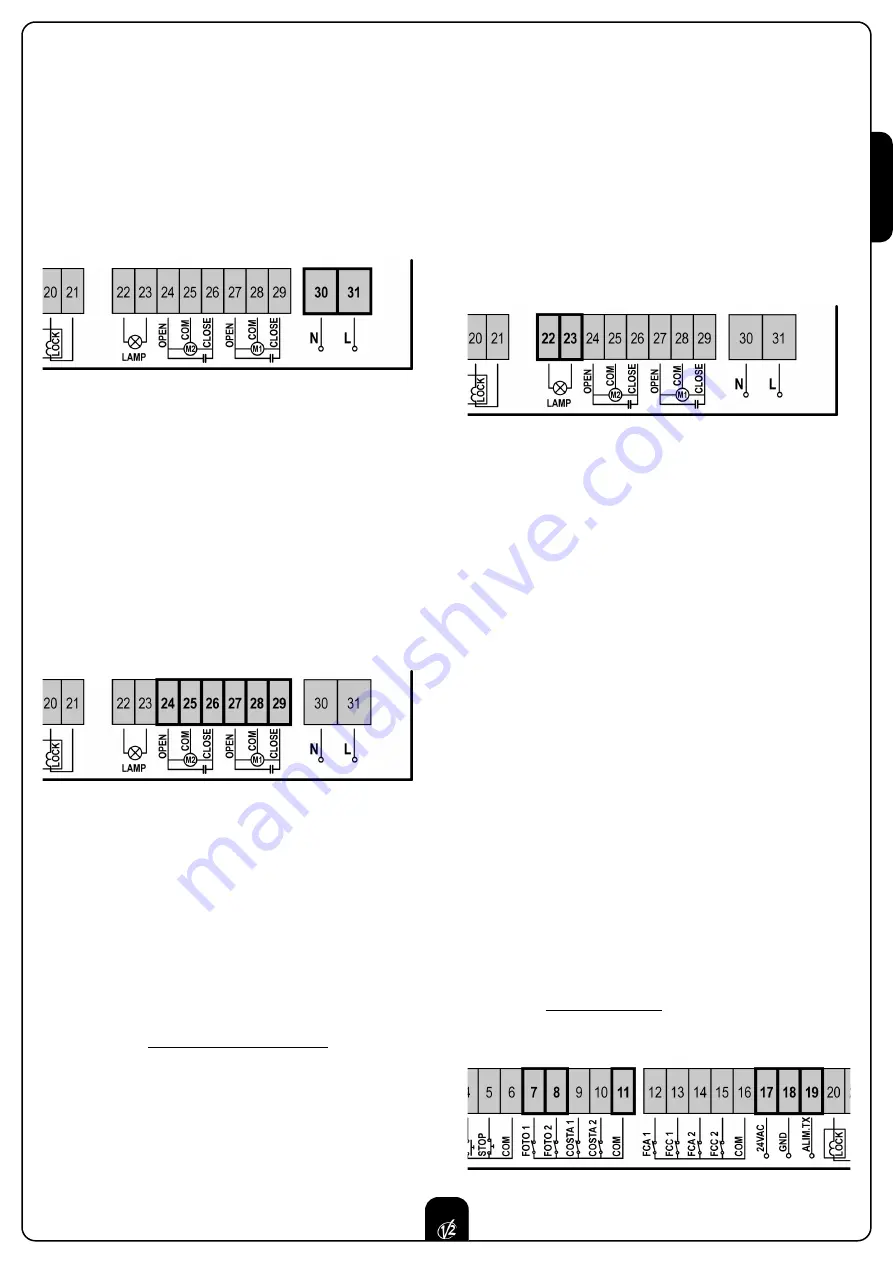
Connect power supply cables to terminals 

30

and 

31

of 

CITY1

control unit.

MOTORS

CITY1

control unit can control one or two alternate current

asynchronous motors. If the control unit needs to control one
motor only, the latter must be connected to terminals of 
motor 1.

Connect motor 1 cables as follows:
• opening cable to terminal 

27

• closing cable to terminal 

29

• common return cable to terminal 

28

Connect motor 2 (if any) cables as follows:
• opening cable to terminal 

24

• closing cable to terminal 

26

• common return cable to terminal 

25

CONTROL OF THE CORRECT ORDER OF CLOSING
LEAVES

If the leaves of the gate overlap during the closing phase, it is
necessary to connect the motor of the leaves that must start first
at the motor 1 terminals, and to arrange the delays (parameters
r.AP and r.Ch) so that collision is avoided. 
If the control unit detects a wrong overlap order (leaf 1 gets to
the closing position before leaf 2), the gate is opened a little
again so that it can close correctly.
If the leaves do not overlap (e.g. in a double swing gate) set to
zero the opening door delay parameter in order to disable the
control of the right closing order.

WARNING (USING HYDRAULIC MOTORS):

• If using hydraulic motors, the following function could not 

work properly: Soft start, Slowing down and Obstacle sensor. 
In this case, such functions should be disabled from menu.

• Read carefully the working times self-learning procedure, 

described in the paragraph “QUICK CONFIGURATION”, 
paying particular attention to the points where the procedure 
to be followed in case of disabled obstacle sensor is 
described.

WARNING:

• In case it has not yet fitted, a start capacitor for each motor

is required; connect the start capacitor for motor 1 between 
terminals 

27

and 

29

and start capacitor for motor 2 (if any) 

between terminals 

24

and 

26

.

• In case motor 2 is not connected, set menu 

tAP2

to zero.

BLINKER

CITY1

control unit provides for a 230V 40W (120V – 40W for

model 

CITY1-120V

) blinker equipped with intermittence inside.

Connect blinker cables to terminals 

22

and 

23

of the control

unit.

PHOTOCELLS

The control unit considers two kinds of photocells, depending on
the terminal to which they are connected:

Photocell 1:

that is to say, photocells installed on the gate 

inner side, which are active both during the opening and the 
closing phase. When photocells 1 operate, the control unit 
stops the doors; as soon as the photocell beam is free, the 
control unit will open the gate completely.

Photocell 2:

that is to say, photocells installed on the 

external gate side and which are active during the closing
phase only. When photocells 2 operate, the control unit 
opens the gate immediately, without waiting for release.

CITY1

control unit supplies a 24VAC power supply to photocells

and it can perform a photocell operation test before starting the
gate opening phase. Photocell power terminals are 
protected by an electronic fuse that stops current in case of
overload.

• Connect power supply cables of photocells transmitter 

between terminals 

19

and 

18

of the control unit.

• Connect power supply cables of photocells receiver between 

terminals 

17

and 

18

of the control unit.

• Connect receiver output of photocells 1 between terminals 

7

and 

11

of the control unit and receiver output of photocells 

2 between terminals 

8

and 

11

of the control unit. 

Use outputs having normally closed contact. 

WARNING:

• if several couples of same kind photocells are mounted, 

their outputs must be connected in series.

• In case of reflection photocells, power supply must be 

connected to terminals 

19

and 

18

of the control unit to 

carry out the operation test.

Содержание CITY1

Страница 1: ...IL n 170 1 EDIZ 04 03 2009 V2 S p A Corso Principi di Piemonte 65 67 12035 RACCONIGI CN ITALY tel 39 01 72 81 24 11 fax 39 01 72 84 050 info v2home com www v2home com CITY1 I...

Страница 2: ...Y RIBBONS 28 LOCK 28 END OF STROKE 28 ENCODER 28 STOP 28 ACTIVATION INPUTS 29 EXTERNAL AERIAL 29 PLUG IN RECEIVER 29 OPTIONAL MODULES 29 CONTROL PANEL 30 USE OF DOWN MENU AND UP KEYS FOR PROGRAMMING 3...

Страница 3: ...N 12453 allows We recommend to make use of an emergency button to be installed by the automation connected to the control unit STOP input so that the gate may be immediately stopped in case of danger...

Страница 4: ...d in case of disabled obstacle sensor is described WARNING In case it has not yet fitted a start capacitor for each motor is required connect the start capacitor for motor 1 between terminals 27 and 2...

Страница 5: ...good closing of doors Make use of a 12V lock Connect lock cables to terminals 20 and 21 of the control unit END OF STROKE CITY1 control unit supports the two following kinds of end of stroke end of s...

Страница 6: ...f device controlling the first input between terminals 3 and 6 of the control unit Connect cables of device controlling the second input between terminals 4 and 6 of the control unit The first input f...

Страница 7: ...nto its closing phase If it blinks it means that the closing has been caused by a safety device border or obstacle detector USE OF DOWN MENU AND UP KEYS FOR PROGRAMMING Control unit time and function...

Страница 8: ...the doors will be activated in closing direction until the stop end or the closing end of stroke is reached Be sure that the leaves do not overlap In case NEITHER the ends of stroke NOR the obstacle s...

Страница 9: ...ning phase before the relevant time expires WARNING if motor 2 is not connected this time must be set to zero in this circumstance the control unit will not consider all configurations of motor 2 and...

Страница 10: ...mmand it will use this time to close the gate Max allowed time to be setup is t CH1 To avoid that the door does not close completely we recommend to setup a longer time than t APP opening time Leaf 2...

Страница 11: ...motors to help the electric lock release The control unit controls the motors in reduced power in closing direction for the setup time The backlash precedes the electric lock release It is possible t...

Страница 12: ...down function in order to measure both opening and closing times and to enable it again once the setup has been carried out The control unit will automatically consider the working time delay caused b...

Страница 13: ...the step by step operation logic Select option APEr to set up the always open operation logic Start command during the pause This menu allows fixing the control unit conduct in case it receives a Sta...

Страница 14: ...n is disabled by setting the value to zero no will be displayed the gate can be closed through the start command only in this case St PA menu setup will be ignored If the control unit receives a Stop...

Страница 15: ...ns associated to the command of STOP no The input STOP is not available ProS The input STOP stops the gate pressing the command START the gate continues the motion invE The command STOP stops the gate...

Страница 16: ...In some installations it may occur that the gate door passes before the photocells so breaking their beam In this case the gate cannot complete its closing cycle Through this function photocells can...

Страница 17: ...eached its position of complete opening or closing no End of stroke inputs are disabled Si End of stroke inputs are enabled Motor Release on Mechanical Stop When the gate halts against the mechanical...

Страница 18: ...exactly to the starting position it is possible to set an anti skid time that is added to the time calculated by the control unit in order to recover the inertia WARNING If function ASM is disabled t...

Страница 19: ...d the learning cycle starts WARNING The procedure of the operation time automatic learning can be starter only if the Start inputs are set up on the STANDARD mode StAn End of Programming This menu all...

Страница 20: ...cles after which the next service will be requested In case no new value is setup that is to say that the counter value is left at zero the signalling function for the service request will be disabled...

Страница 21: ...0 no Pre flashing disabled it corresponds to 0 Pot1 30 100 Motor 1 power 60 60 Pot2 30 100 Motor 2 power 60 SPUn no Si Start off no Si t P So 0 5 3 0 Slowed down starting time 1 5 no no Slowed down s...

Страница 22: ...no no no Function disabled F ShA FOTO2 disabling higher time i ShA FOTO2 disabling lower time CoS1 no Si Border 1 input fixed border no no CoS2 no Si Border 2 input mobile border no no FC En no Si En...

Страница 23: ...ing phase N C contact 16 Common 17 18 Power output 24 VAC for photocells and other accessories 18 19 Photocell TX power supply for functional test 20 21 Electric lock 12VAC 22 23 Flashing light 230VAC...

Страница 24: ...K 2 x 1 5 mm2 PG9 For cables with external from 5 to 8 mm OTHER WIRINGS MULTIPOLAR n x 0 25 0 5 mm2 n depending on the number of wirings to be made PG9 For cables with external from 5 to 8 mm PG11 For...

Страница 25: ...sure that photocells are powered and working when you interrupt their beam you should hear the relay tripping Error 4 After few centimeters during the opening phase the gate stops and the display show...

Страница 26: ...V2 S p A Corso Principi di Piemonte 65 67 12035 RACCONIGI CN ITALY tel 39 01 72 81 24 11 fax 39 01 72 84 050 info v2home com www v2home com...

Отзывы: