V2 CITY1 Скачать руководство пользователя страница 6

E

N

G

L

IS

H

29

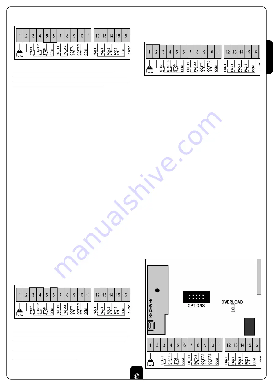
Connect the stop switch cables between terminal 

5

and 

6

of the

control unit.

The stop switch function can be activated by means of a 
remote control stored on channel 3 (see relevant instructions of
MR1 receiver). The command STOP from remote is operative also
if the input STOP of the terminal board is disabled.

ACTIVATION INPUTS

CITY1

control unit is equipped with two activation inputs, whose

operation depends on the programmed operation modes (see

Strt

item of programming menu):

Standard mode:

a command being on the first input will 

cause the complete opening of both leaves (start); a 
command being on the second input will cause the partial 
opening of leaf 1 only (pedestrian start).

Open/Close command and manned operation:

a command on the first input always controls the gate 
opening, while a command on the second input always 
controls the gate closing. 
In Open/Close mode, there is an impulse command, that is 
to say that an impulse will cause the complete gate opening 
or closing. 
In manned operation, there is a monostable command, that 
is to say, the gate will be opened or closed as long as the 
contact is closed and it will immediately stop as the contact 
is open.

Timer mode:

it is similar to the standard mode but the gate

stays open (completely or partially) while the contact is 
closed on input; as soon as the contact is open the pause 
time count down will start, after which the gate will be 
closed again. This function allows programming the gate 
opening time during the day, by making use of an external 
timer. Automatic closing must be enabled.

In all modes, inputs must be connected to devices having 
normally open contacts.

Connect cables of device controlling the first input between 
terminals 

3

and 

6

of the control unit.

Connect cables of device controlling the second input between
terminals 

4

and 

6

of the control unit.

The first input function can also be activated by pressing UP key
outside the programming menu or by means of a remote control
stored on channel 1 (see relevant instructions of MR1 receiver).

The second input function can also be activated by pressing
DOWN key outside the programming menu or by means of a
remote control stored on channel 2.

EXTERNAL AERIAL

We suggest to use the external aerial (model ANSGP433) in order
to guarantee the maximal range.
Connect the antenna hot pole to terminal 

1

of the control unit

and the braiding to terminal 

2

.

PLUG IN RECEIVER

CITY1

control unit is suitable for plugging in a Personal Pass MR1

receiver having a high-sensitivity super-heterodyne architecture.

WARNING:

it is necessary to turn off the control unit 

power before doing the operations mentioned here below. 
Pay attention to the way you connect the removable modules.

MR1 module receiver is provided with 4 channels and each of
them is suitable for a command of 

CITY1

control unit:

• CHANNEL  1

쩚쩛

START

• CHANNEL  2

쩚쩛

PEDESTRIAN START 

• CHANNEL  3

쩚쩛

STOP

• CHANNEL  4

쩚쩛

OPTIONAL MODULS OUTPUT 

WARNING:

Before programming 4 channels and function 

logics read carefully the instructions of MR1.

OPTIONAL MODULES

The 

CITY1

digital control unit, besides its excellent versatility,

provides for the final user with the possibility to add new 
functions by means of optional modules. Its dedicated 
connector has been placed over the word 

OPTIONS

WARNING:

Please read the instructions of each single

module to install the optional modules.

Connector for optional modules can also be used to plug in the
programming lock key (cod. 

CL1

), which prevents from any 

operation set-up change by non-authorized personnel.

Содержание CITY1

Страница 1: ...IL n 170 1 EDIZ 04 03 2009 V2 S p A Corso Principi di Piemonte 65 67 12035 RACCONIGI CN ITALY tel 39 01 72 81 24 11 fax 39 01 72 84 050 info v2home com www v2home com CITY1 I...

Страница 2: ...Y RIBBONS 28 LOCK 28 END OF STROKE 28 ENCODER 28 STOP 28 ACTIVATION INPUTS 29 EXTERNAL AERIAL 29 PLUG IN RECEIVER 29 OPTIONAL MODULES 29 CONTROL PANEL 30 USE OF DOWN MENU AND UP KEYS FOR PROGRAMMING 3...

Страница 3: ...N 12453 allows We recommend to make use of an emergency button to be installed by the automation connected to the control unit STOP input so that the gate may be immediately stopped in case of danger...

Страница 4: ...d in case of disabled obstacle sensor is described WARNING In case it has not yet fitted a start capacitor for each motor is required connect the start capacitor for motor 1 between terminals 27 and 2...

Страница 5: ...good closing of doors Make use of a 12V lock Connect lock cables to terminals 20 and 21 of the control unit END OF STROKE CITY1 control unit supports the two following kinds of end of stroke end of s...

Страница 6: ...f device controlling the first input between terminals 3 and 6 of the control unit Connect cables of device controlling the second input between terminals 4 and 6 of the control unit The first input f...

Страница 7: ...nto its closing phase If it blinks it means that the closing has been caused by a safety device border or obstacle detector USE OF DOWN MENU AND UP KEYS FOR PROGRAMMING Control unit time and function...

Страница 8: ...the doors will be activated in closing direction until the stop end or the closing end of stroke is reached Be sure that the leaves do not overlap In case NEITHER the ends of stroke NOR the obstacle s...

Страница 9: ...ning phase before the relevant time expires WARNING if motor 2 is not connected this time must be set to zero in this circumstance the control unit will not consider all configurations of motor 2 and...

Страница 10: ...mmand it will use this time to close the gate Max allowed time to be setup is t CH1 To avoid that the door does not close completely we recommend to setup a longer time than t APP opening time Leaf 2...

Страница 11: ...motors to help the electric lock release The control unit controls the motors in reduced power in closing direction for the setup time The backlash precedes the electric lock release It is possible t...

Страница 12: ...down function in order to measure both opening and closing times and to enable it again once the setup has been carried out The control unit will automatically consider the working time delay caused b...

Страница 13: ...the step by step operation logic Select option APEr to set up the always open operation logic Start command during the pause This menu allows fixing the control unit conduct in case it receives a Sta...

Страница 14: ...n is disabled by setting the value to zero no will be displayed the gate can be closed through the start command only in this case St PA menu setup will be ignored If the control unit receives a Stop...

Страница 15: ...ns associated to the command of STOP no The input STOP is not available ProS The input STOP stops the gate pressing the command START the gate continues the motion invE The command STOP stops the gate...

Страница 16: ...In some installations it may occur that the gate door passes before the photocells so breaking their beam In this case the gate cannot complete its closing cycle Through this function photocells can...

Страница 17: ...eached its position of complete opening or closing no End of stroke inputs are disabled Si End of stroke inputs are enabled Motor Release on Mechanical Stop When the gate halts against the mechanical...

Страница 18: ...exactly to the starting position it is possible to set an anti skid time that is added to the time calculated by the control unit in order to recover the inertia WARNING If function ASM is disabled t...

Страница 19: ...d the learning cycle starts WARNING The procedure of the operation time automatic learning can be starter only if the Start inputs are set up on the STANDARD mode StAn End of Programming This menu all...

Страница 20: ...cles after which the next service will be requested In case no new value is setup that is to say that the counter value is left at zero the signalling function for the service request will be disabled...

Страница 21: ...0 no Pre flashing disabled it corresponds to 0 Pot1 30 100 Motor 1 power 60 60 Pot2 30 100 Motor 2 power 60 SPUn no Si Start off no Si t P So 0 5 3 0 Slowed down starting time 1 5 no no Slowed down s...

Страница 22: ...no no no Function disabled F ShA FOTO2 disabling higher time i ShA FOTO2 disabling lower time CoS1 no Si Border 1 input fixed border no no CoS2 no Si Border 2 input mobile border no no FC En no Si En...

Страница 23: ...ing phase N C contact 16 Common 17 18 Power output 24 VAC for photocells and other accessories 18 19 Photocell TX power supply for functional test 20 21 Electric lock 12VAC 22 23 Flashing light 230VAC...

Страница 24: ...K 2 x 1 5 mm2 PG9 For cables with external from 5 to 8 mm OTHER WIRINGS MULTIPOLAR n x 0 25 0 5 mm2 n depending on the number of wirings to be made PG9 For cables with external from 5 to 8 mm PG11 For...

Страница 25: ...sure that photocells are powered and working when you interrupt their beam you should hear the relay tripping Error 4 After few centimeters during the opening phase the gate stops and the display show...

Страница 26: ...V2 S p A Corso Principi di Piemonte 65 67 12035 RACCONIGI CN ITALY tel 39 01 72 81 24 11 fax 39 01 72 84 050 info v2home com www v2home com...

Отзывы: