


2DA/2DB
2-1-15
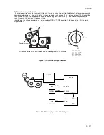
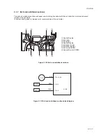
2-1-6 Fixing section
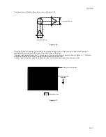
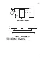
The fixing section consists of the parts shown in figure. When paper reaches the fixing section after the transfer process,
it passes between the press roller and heat roller, which is heated by fixing heaters M and S (FH-M/FH-S). Pressure is
applied by the fixing unit pressure springs so that the toner on the paper is melted, fused and fixed onto the paper. The
heat roller is heated by fixing heaters M and S (FH-M/FH-S) inside it; its surface temperature is detected by the fixing
thermistor (FTH) and is regulated by the fixing heaters turning on and off.
If the fixing section becomes abnormally hot, fixing thermostat (FTS) operates shutting the power to the fixing heaters off.
When the fixing process is completed, the paper is separated from the heat roller by its separation claws and is
conveyed from the MFP to exit and switchback section.
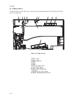
1
Left fixing unit
2
Right fixing unit
3
Press roller
4
Heat roller
5
Fixing heater M (FH-M)
6
Fixing heater S (FH-S)
7
Heat roller separation claw
8
Fixing thermostat (FTS)
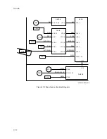
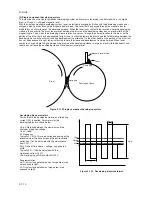
Figure 2-1-18 Fixing section block diagram
Figure 2-1-17 Fixing section
FH-M
FH-M
FTH
FH-S
CN3-12
YC6-2
YC6-1
YC6-3
LIVE
COM
PSPCB
AC
YC2-7
YC2-8
YC21-8
YC21-7
Heat roller
FTS
FTH
EPCB
FH-S
Содержание cd 1116
Страница 1: ...Service Manual Copy CD 1116 CD 1120 Rev 1 ...
Страница 2: ...Service Manual Copy DC 2116 DC 2120 Rev 1 ...
Страница 4: ...This page is intentionally left blank ...
Страница 247: ...2DA 2DB 1 2 3 2 Figure 2 3 2 Power source PCB silk screen diagram 220 240 V AC 120 V AC ...
Страница 264: ...2DA 2DB 1 2 3 19 Figure 2 3 10 Operation unit PCB silk screen diagram ...


