


2DA/2DB
1-4-49
Maintenance
Description
item No.
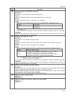
U917
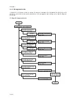
Setting backup data reading/writing
Description
Stores backup data from the fax control PCB (when an optional fax kit is installed) into Compact Flash or reads
the data from Compact Flash.
Purpose
To store and write data when replacing the PCB.
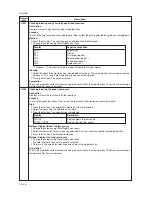
Setting
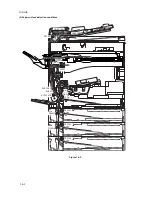
1. Turn the power switch off and disconnect the power plug.
2. Remove the rear cover.
3. Insert Compact Flash in a notch hole of the machine.
4. While pressing the Copier key, turn on the power switch and connect the power plug.
Press and hold on the Copier key until the message “Please wait.” disappears.
5. Enter the maintenance item.
6. Press the start key. The screen for selecting an item is displayed.
7. Select the item using the up/down cursor keys. The selected item is displayed in reverse.
Display
Description
SRAM
→
CF:BKUP
Writing the backup data of fax control PCB
CF
→
SRAM:BKUP
Reading the backup data of fax control PCB
SRAM
→
CF:DIAL
Writing the backup data of fax dial information
CF
→
SRAM:DIAL
Reading the backup data of fax dial information
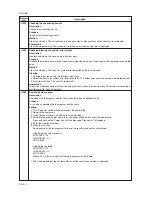
8. Press the start key. Reading or writing is executed, and the screen displays the result.
• If the operation was successful:
EXECUTE 0100
CHECK SUM
∗∗∗∗
CODE 0000
• If the operation failed:
EXECUTE 0100
CHECK SUM
∗∗∗∗
CODE XXXX
Where XXX is the error code indicating the reason for the failure.
See “Error Codes for Operation U917 and U926” below.
9. Turn the power switch off and disconnect the power plug.
10. Remove the Compact Flash from the machine.
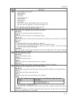
Detects call for service on fax control PCB.
Communication error.
Detects call for service on main PCB.
CF error.
No CF card.
No data in CF card.
CF data is incompatible.
Bad CF data (Checksum error)
CF read error.
CF write error.
Fax control PCB flash memory error.
0102
0104
0105
01FF
0202
0203
0204
0205
0206
0207
0212
Code
Meaning
Error Codes for Operation U917 and U926
Содержание cd 1116
Страница 1: ...Service Manual Copy CD 1116 CD 1120 Rev 1 ...
Страница 2: ...Service Manual Copy DC 2116 DC 2120 Rev 1 ...
Страница 4: ...This page is intentionally left blank ...
Страница 247: ...2DA 2DB 1 2 3 2 Figure 2 3 2 Power source PCB silk screen diagram 220 240 V AC 120 V AC ...
Страница 264: ...2DA 2DB 1 2 3 19 Figure 2 3 10 Operation unit PCB silk screen diagram ...


