


86
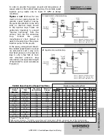
A permanent capacitor, impedance protected motor (no start
switch) on the circulator is required. The maximum allowable
amperage for this output is 2.2 amps, which limits the
allowable circulator size to 1/6 HP.
This type of system can use a small circulator to inject a high
BTU input into a relatively large system flow. Typically, the
injection pump need only deliver 1/6 to 1/4 of the system flow
for low temperature radiant panels if high temperature water
is available for injection. In small hydronic systems, the
smallest available circulator for variable speed injection may
be too large. It is important to properly size the injection pump
and use a globe valve on the return injection leg.
For proper injection pump sizing, the designer must know the
following information:
(See fig. b)
F
V
= Flow Rate (Injection Loop) in GPM
F
1
= Radiant (Secondary Loop) Flow Rate in GPM
T
1
= Boiler (Primary Loop) Supply Temperature
T
2
= Radiant (Secondary Loop) Supply Temperature
T
R
= Radiant (Secondary Loop) Return Temperature
T
D
= Radiant (Secondary Loop) Temperature
Differential (
T
2
-
T
R
)
Note:
All values are to be given at design
conditions. The formula used for sizing the
injection pump is shown below.
F
V
= (
F
1
x
T
D
)
/
(
T
1
-
T
R
)
Example:
If values at design conditions are:
F
1
= Radiant (Secondary) Flow = 30 GPM
T
1
= Boiler (Primary) Supply = 180°F
T
2
= Radiant (Secondary) Supply = 140°F
T
R
= Radiant (Secondary) Return = 120°F
T
D
= Radiant (Secondary) Differential = 20°F
To find the injection pump flow rate:
F
V
= (30 x 20)
/
(180 - 120)
F
V
= (600)
/
(60)
F
V
= 10 GPM
APPENDIX I
APPENDIX I - Variable Speed Injection Mixing
b
Direct Injection Mixing
“F
V
” to be calculated
Variable
Speed
Injection
Pump
Supply To LOW
Temperature Loop
T
2
F
1
Supply From HIGH
Temperature Loop
T
1
T
R
F
1
“DIRECT” INJECTION
F
V
F
V
T
D
Direct Injection
F
V
= (
F
1
x
T
D
) / (
T
1
-
T
R
)
Содержание SYSTEMpro 311
Страница 1: ...SYSTEMpro 311 Installation Manual...
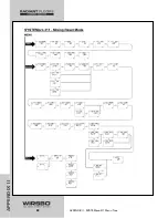
Страница 44: ...PROGRAMMING THE ADJUST MENU B DHW SETTINGS 42 PROGRAMMING PROGRAMMING Step 1 Programming the Control...
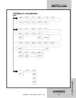
Страница 52: ...PROGRAMMING THE ADJUST MENU D SNOW MELTING SETTINGS 50 PROGRAMMING PROGRAMMING Step 1 Programming the Control...
Страница 56: ...PROGRAMMING THE ADJUST MENU E BOILER OPERATION 54 PROGRAMMING PROGRAMMING Step 1 Programming the Control...
Страница 90: ...88 APPENDIX II APPENDIX II SYSTEMpro 311 Menu Tree...
Страница 91: ...89 APPENDIX II APPENDIX II SYSTEMpro 311 Menu Tree...
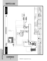
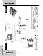
Страница 92: ...90 APPENDIX III APPENDIX III Application Drawings...
Страница 93: ...91 APPENDIX III APPENDIX III Application Drawings...
Страница 94: ...92 APPENDIX III APPENDIX III Application Drawings...
Страница 95: ...93 APPENDIX III APPENDIX III Application Drawings...
Страница 96: ...94 APPENDIX III APPENDIX III Application Drawings...
Страница 97: ...95 APPENDIX III APPENDIX III Application Drawings...
Страница 98: ...96 APPENDIX III APPENDIX III Application Drawings...
Страница 99: ...97 APPENDIX III APPENDIX III Application Drawings...
Страница 106: ......