


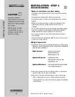


INSTALLATION - STEP 3
ROUGH-IN WIRING
Things to note before you start wiring:
• All electrical wiring should end in the control base wiring
chamber
• The base has standard 7/8” (22 mm) knockouts
• Knockouts accept common wiring hardware and conduit
fittings
• Before removing knockouts, check wiring diagram and
select those sections of the chamber with common
voltages
• Do not allow the wiring to cross between low/high voltage
sections or else wires will interfere with safety dividers
(these dividers should be installed at a later time)
• Do not apply power to any of the wires during rough-in
wiring stage
• All wires should be stripped to 3/8"L (9 mm) for the correct
connection to the control
Wiring Components:
1) Install the various sensors indicated below as per instructions
listed and run the wiring back to the control base and label all
wires for later installation
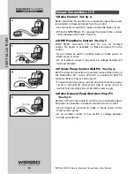
Main Sensors:
• Outdoor Sensor S4
• Boiler Sensor S3
• Mixing Sensor S1
Optional Sensors:
• DHW Sensor S6
• Mixing Return Sensor S5
• Slab Sensor S7
Optional Modules:
• Remote Display Module (RDM)
• Snow Melt Enable Kit
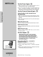
2) Run appropriate wire from all other system components
(pump, boiler, etc.) to the control base
3) Run wires from the 120 VAC power to the control base
• Use a clean power source to ensure proper operation
• Comply with local codes for minimum gauge and breaker
requirements
18
INST
ALLA
TION
INSTALLATION - Step 3 - Rough-In Wiring
CAUTION
All wiring must be
performed by a licensed
professional and comply
with local trade practices
and codes.
Wirsbo does not take
responsibility for any
damage caused due to
failure to comply.
Содержание SYSTEMpro 311
Страница 1: ...SYSTEMpro 311 Installation Manual...
Страница 44: ...PROGRAMMING THE ADJUST MENU B DHW SETTINGS 42 PROGRAMMING PROGRAMMING Step 1 Programming the Control...
Страница 52: ...PROGRAMMING THE ADJUST MENU D SNOW MELTING SETTINGS 50 PROGRAMMING PROGRAMMING Step 1 Programming the Control...
Страница 56: ...PROGRAMMING THE ADJUST MENU E BOILER OPERATION 54 PROGRAMMING PROGRAMMING Step 1 Programming the Control...
Страница 90: ...88 APPENDIX II APPENDIX II SYSTEMpro 311 Menu Tree...
Страница 91: ...89 APPENDIX II APPENDIX II SYSTEMpro 311 Menu Tree...
Страница 92: ...90 APPENDIX III APPENDIX III Application Drawings...
Страница 93: ...91 APPENDIX III APPENDIX III Application Drawings...
Страница 94: ...92 APPENDIX III APPENDIX III Application Drawings...
Страница 95: ...93 APPENDIX III APPENDIX III Application Drawings...
Страница 96: ...94 APPENDIX III APPENDIX III Application Drawings...
Страница 97: ...95 APPENDIX III APPENDIX III Application Drawings...
Страница 98: ...96 APPENDIX III APPENDIX III Application Drawings...
Страница 99: ...97 APPENDIX III APPENDIX III Application Drawings...
Страница 106: ......