background image

 45 


3. 

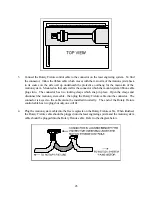
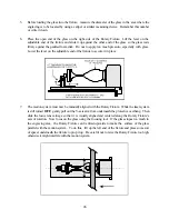
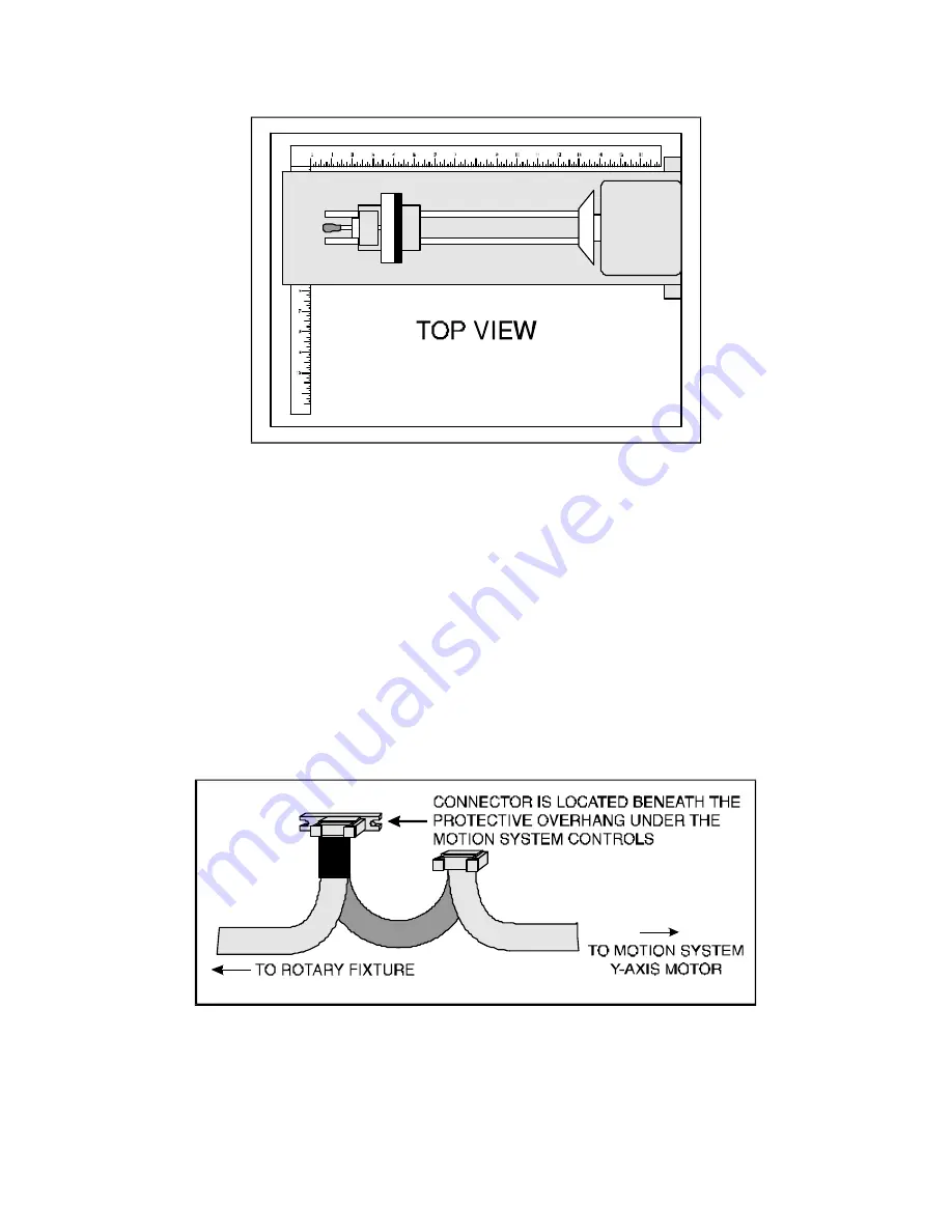
Connect the Rotary Fixture control cable to the connector on the laser engraving system.  To find 
the connector,  follow the ribbon cable which moves with the main arm of the motion system back 
to its source on the side wall up underneath the protective overhang for the main arm of the 
motion system.  Mounted on that side wall is the connector which the motion system ribbon cable 
plugs into.  The connector has two locking clasps which snap in place.  Open the clasps and 
disconnect the motion system cable,  then plug the Rotary Fixture cable into the connector.  The 
connector is keyed so the cable cannot be installed incorrectly.  The end of the Rotary Fixture 
control cable has two plugs but only one will fit. 

 
4. 

Plug the motion system cable into the free receptacle on the Rotary Fixture cable.  When finished,  
the Rotary Fixture cable should be plugged into the laser engraving system and the motion system 
cable should be plugged into the Rotary Fixture cable.  Refer to the diagram below. 


Содержание ULS-25

Страница 1: ...OPERATION MANUAL ULS 25 LASER SYSTEM Universal Laser Systems Inc 16008 North 81st Street Scottsdale AZ 85260 Phone 602 483 1214 Fax 602 483 5620 Volume I Rev 6 April 1995...

Страница 2: ...ICS SOFTWARE 16 3 2 THE ULS WINDOWS PRINTER DRIVER 21 3 3 USING DOS BASED PROGRAMS 26 SECTION 4 LASER SYSTEM OPERATION 4 1 GENERAL SYSTEM OVERVIEW 27 4 2 THE MAIN CONTROL PANEL 28 4 3 MOTION SYSTEM CO...

Страница 3: ...3 APPENDIX E SOFTWARE ANOMALIES E...

Страница 4: ...Universal Laser Systems Inc UNIVERSAL LASER SYSTEMS INC 1994 ALL RIGHTS RESERVED NOTICE Universal Laser Systems Inc does not assume any liability arising out of the application or use of any products...

Страница 5: ...r system The manual includes important information about the safety assembly use and maintenance of the laser system We cannot overemphasize the importance of reading the owner s manual completely Whe...

Страница 6: ...vere eye damage Proper use and care of this system is very important to the safety of all people in the surrounding area 2 Exposure to the laser beam may cause ignition of combustible materials so a p...

Страница 7: ...ations at the time of manufacture These labels are not to be removed If they become damaged or removed for any reason please request additional labels from Universal Laser Systems they will be provide...

Страница 8: ...er the front or top door is opened This interlock system is connected in series with a switch and a red indicator light on the control panel of the system The switch allows the power to the laser to b...

Страница 9: ...efully remove the foam which protects the viewing window on the top of the system and remove the tape which holds the top door in place 4 Remove the box containing the two cart legs This box is shippe...

Страница 10: ...hould face forward see figure below Assemble cart with lockable casters in front Use 10 32 screws and lock washers View is from the back side of the cart Cart Assembly 8 When the cart is assembled pos...

Страница 11: ...tion or electrical noise We recommend using a high quality surge protector 15 Amp capability to protect the laser engraving system s electronics m Avoid small enclosed areas where ventilation is poor...

Страница 12: ...should be used between the blower unit and the laser system The exhaust tubing should be smooth walled and have as few bends as possible Use duct work with a diameter that matches the blower unit and...

Страница 13: ...llation of the exhaust system by a licensed contractor to meet safety and local code requirements Please contact a local air quality control specialist Again if there are any questions please contact...

Страница 14: ...14 Sample Exhaust System Layouts...

Страница 15: ...s except Windows 3 1 and a Windows graphics program would not be necessary 2 5 LASER SYSTEM INSTALLATION CAUTION Please make the following connections in the exact order described otherwise static ele...

Страница 16: ...ft Windows works is essential to the operation of the laser system Please consult the Windows owner s manual on its installation use and operation before continuing Installation Procedure for the ULS...

Страница 17: ...driver should now install itself and the laser system should appear in the Installed Printer dialog box 7 Highlight the laser system and click on Connect Select the port the laser system is attached...

Страница 18: ...d engrave or cut more than one object at a time This is accomplished by duplicating the image on screen as many times as necessary to fill up the entire page Ruler Setup Usually the graphics software...

Страница 19: ...sentation of the pink color s lighter shade To prevent the incorrect assignment of laser power be sure to use the right colors If using graphics with colors other than the eight listed above or to sim...

Страница 20: ...ct the outline in the graphics software and send it to the back behind the other objects to cause the outline to be cut first Bringing the outline to the front will cause that outline to cut last A fi...

Страница 21: ...into the graphics program If the artwork contains engraved objects of the same color with a great deal of space between them in the engraving direction processing time can be longer since the laser mu...

Страница 22: ...he laser system cut out a bitmap is to first convert it to a vector file format such as an EPS Raster to vector conversion programs are available that trace the bitmap this only works well with monoch...

Страница 23: ...tton This will highlight the color and allow changing of the settings by using the scroll bars or highlighting out and typing in each setting It is possible to set one color at a time or click on addi...

Страница 24: ...ing the PPI to 500 and using a standard lens that has a laser spot size of seven thousandths of an inch significant pulse overlap will occur The laser system fires a laser pulse and moves over two tho...

Страница 25: ...print If the bitmap does not engrave go back and turn the switch ON select the bitmap only and print Selected Objects Only in the software Make sure to leave this switch OFF if there is no bitmap pre...

Страница 26: ...he pattern will need to be specified Refer to the imaging software for more details about the direct printing of halftone patterns SOFTWARE OVERRIDE Leave this switch turned ON at all times if plannin...

Страница 27: ...etup file These files can be stored in any directory and may be retrieved by selecting FILE and then LOAD SETUP FILE The LASER INI file can be thought of as being a file that stores the current power...

Страница 28: ...g a few tests to see where the laser system will output 2 Some DOS programs use the lower left corner of the engraving field as the origin so remember this when setting up the graphic drawing 3 When a...

Страница 29: ...l Socket 3 Top Door Counterbalances 11 Air Intake Filter 4 Engraving Table Adjustment Knob 12 Parallel and Serial Connectors On Off 5 Focus Lens Holder Assembly Switch Power Cord Inlet 6 Motion System...

Страница 30: ...sor on the desired item press the SELECT key to access that item The ESCAPE key allows backing up through the menu system to the main menu The ESCAPE and SELECT buttons also function for changing a se...

Страница 31: ...stantly jumping from menu to menu is not needed The first line indicates that the laser system s print buffer is empty but when the buffer is loaded with files this line will display the currently sel...

Страница 32: ...ing that the laser system is processing When the laser system is first powered on and this submenu is selected there will be an initial power setting displayed Even after the first file is downloaded...

Страница 33: ...T key again to bring the cursor over to the left hand side of the display and proceed to m ake the adjustments as previously described If setting the PPI higher than 1000 the laser system will display...

Страница 34: ...he beginning of the next file and to calculate the remaining free buffer space Without an EOF the buffer will not operate properly There are two ways that a downloaded file will have a missing EOF The...

Страница 35: ...the plasma inside energized This allows the laser to respond quickly for high speed cutting and engraving The tickle is preset at the factory and usually will not require adjusting However as the las...

Страница 36: ...ngs while it is cutting and engraving a file If this feature is ON the default setting the power settings will change in response to different colors used in the artwork or in the case of DOS applicat...

Страница 37: ...oftware manuals for details on setting up the computer s serial port If using the SERIAL port select the fastest possible BAUD rate for communication since this effects how quickly the computer can se...

Страница 38: ...other submenus It may be necessary to use the diagnostic tests if instructed to do so by a member of the ULS technical support staff The first line on the menu display is a buffer memory test but in...

Страница 39: ...AND RESUME PAUSE and RESUME The PAUSE button can be pressed while the system is cutting or engraving a file to pause all operations When paused the motion system arm will move to its home position und...

Страница 40: ...e functions of the keys are described below POSITIONING KEYS Use these keys to move the motion system in the indicated direction Pressing two adjacent keys together moves the focus lens carriage in a...

Страница 41: ...ation a template can be easily made to help in loading the system To make a template draw a slightly oversized outline of the material to be processed and duplicate it as many times as will fit into t...

Страница 42: ...tly so the focusing tool again sets flat against the side of the lens holder The point in which the focusing tool just starts to tilt away is the optimal focus distance NOTE The focal length of the op...

Страница 43: ...r for loading STEP 3 By using the motion system control keys position the focus lens assembly over the engraving material Adjust focus by using the focusing tool and adjusting the height of the engrav...

Страница 44: ...igned to hold wine glasses mugs cups etc The following is a step by step procedure in the installation and operation of the Rotary Fixture We are going to use a glass as an example Installation of the...

Страница 45: ...o The connector has two locking clasps which snap in place Open the clasps and disconnect the motion system cable then plug the Rotary Fixture cable into the connector The connector is keyed so the ca...

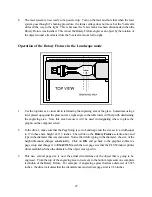
Страница 46: ...to secure it in place 7 The motion system must now be manually aligned with the Rotary Fixture While the laser system is still turned OFF gently pull out the Y axis arm from underneath the protective...

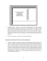
Страница 47: ...ed in designating where to place the graphic on the computer screen 2 In the driver make sure that the Page Setup is set to Landscape and the size set to a width equal to 17 inches and a height of 11...

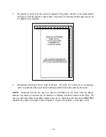
Страница 48: ...ng Operation of the Rotary Fixture in the Portrait mode 1 The Rotary Fixture can also operate in the Portrait mode providing that the engraving object is not too heavy The Portrait mode will cause the...

Страница 49: ...is the same as in Landscape mode Experiment with using both the Landscape and Portrait modes and note the results NOTE Remember that the new page size that was established by the driver when the objec...

Страница 50: ...ches in the Landscape mode In this way we can output to a paper printer before engraving for proofreading Do not use the full 17 x 11 5 inch size for one or a couple of stamps because printing time wi...

Страница 51: ...l inside the laser system respectively After making all driver selections print the graphic to the laser system Start engraving and notice that the stamps are being engraved as a mirrored image and ar...

Страница 52: ...t location on the engraving table and begin engraving The driver automatically mirrors the entire page profiles all of the characters and creates a negative image for engraving Printing Speed When pri...

Страница 53: ...2 and the HIGH RESOLUTION switch in the driver turned ON except were otherwise noted When using a larger fill spacing in order to achieve greater engraving speeds remember that the resolution will be...

Страница 54: ...th sides with water from a spray bottle Elevate the material at least 1 8 off of the engraving table ADDITIONAL COMMENTS There are two types of acrylic available cast and extruded Cast turns white or...

Страница 55: ...ows the smoke and heat to escape from underneath If cutting directly on the engraving table the trapped heat might cause the bottom edge of the cut to pit and distort Re masking and dampening with wat...

Страница 56: ...ENGRAVING fast 5 10 500 1 005 COMMENTS Again masking is not necessary because the acrylic is protected from smoke damage by the mirrored backing TYPE POWER SPEED PPI PASSES DEPTH VECTOR CUTTING 50 1...

Страница 57: ...off of the mirrored surface because it is absorbed by the acrylic first Sometimes cutting the acrylic from the back side will cause the mirrored backing to distort and crack from the intense heat req...

Страница 58: ...r because the anodized will either be dull in appearance or the engraving lines will be too thick TYPE POWER SPEED PPI PASSES DEPTH VECTOR ENGRAVING fast 2 1 500 1 001 COMMENTS Different anodized coat...

Страница 59: ...move the metal when engraving which gives the brass a shine without polishing Brass that is produced for the laser engraving industry is polished then clear coated and finally coated with paint When l...

Страница 60: ...60 different vendors as not all of them will work properly Apply the same parameters and engraving techniques when using coated aluminum...

Страница 61: ...COMMENTS Laser engraving this type of material produces spectacular results especially when the engraved area is paint filled If paint filling it is a good idea to mask first and then engrave through...

Страница 62: ...62...

Страница 63: ...asked TYPE POWER SPEED PPI PASSES DEPTH VECTOR ENGRAVING 10 10 500 1 010 COMMENTS Engrave unmasked TYPE POWER SPEED PPI PASSES DEPTH VECTOR CUTTING 50 1 100 1 060 COMMENTS Unmasked A low PPI setting i...

Страница 64: ...0 COMMENTS Again since glass will not vaporize it does not require a lot of laser power ADDITIONAL COMMENTS Glass engraving is different from other types of engraving A CO2 laser cannot engrave into t...

Страница 65: ...60 1 200 1 100 COMMENTS Cut unmasked A low PPI setting is used to prevent flaming when cutting ADDITIONAL COMMENTS Leather is a very simple material to engrave and most types of leather engrave very w...

Страница 66: ...aving deeply will cause a highly detailed image to appear washed out The objective is to engrave deep enough to turn the marble white and provide a good contrast Too much power can also cause the mate...

Страница 67: ...n excellent material to use for architectural modeling and for picture framing It cuts and engraves very neatly and cleanly It comes in a variety of shades and colors Patterns can be engraved on the s...

Страница 68: ...ADDITIONAL COMMENTS Engraving melamine is very similar to engraving regular wood with the added benefit of a consistent surface finish and uniform base material composition Unlike regular wood which...

Страница 69: ...69 engraving photographs or highly detailed images produces exceptional results Refer to the next example on engraving photographs and or ClipArt...

Страница 70: ...erns including frequency of lines per inch and pattern angles Use a line frequency above 20 and below 100 The size of the dots decreases as the line frequency increases Experiment to see which pattern...

Страница 71: ...utting thicker plastics ADDITIONAL COMMENTS Engravers plastic comes in many different colors thicknesses coatings and surface textures About 75 of the available engravers plastic including ADA signage...

Страница 72: ...72 necessary Be creative when engraving this type of material because amazing results will be produced that cannot be reproduced with a mechanical engraver...

Страница 73: ...limsy and will collapse while stamping them If you do not have this option and would like to add it to your system please contact one of our engineers in the sales department for current pricing All l...

Страница 74: ...ueegee to remove trapped air bubbles The transfer tape can then be lifted off and the vinyl lettering or objects that were vector cut will stick to the transfer tape and maintain their correct spacing...

Страница 75: ...ENGRAVING 25 10 500 1 030 COMMENTS Engrave unmasked TYPE POWER SPEED PPI PASSES DEPTH VECTOR CUTTING 50 1 500 1 125 COMMENTS Elevate at least 1 8 off of the engraving table Lightly dampen bottom side...

Страница 76: ...ite For engraving softer woods such as pine or balsa reduce the power settings to acquire the best depth Engraving too deep on soft woods will reduce quality Every type of wood will engrave differentl...

Страница 77: ...res General cleaning procedure 1 Ensure that the system is turned off and unplugged and open the top door 2 Thoroughly remove all loose dirt and debris from inside the machine 3 With the engraving tab...

Страница 78: ...withstand repeated cleanings if cleaned properly A visual inspection of the mirrors and lens should be performed at least once a day If a haze or debris is present on the optical surfaces they should...

Страница 79: ...cleaning solution to one surface of the lens Let it sit for approximately one minute and then gently wipe the surface using several sheets of lens tissue soaked with lens cleaning solution 8 Dry that...

Страница 80: ...sit for approximately one minute 4 Use a folded piece of lens tissue soaked in lens cleaning solution and gently wipe it across the mirror once Use new lens tissue soaked in lens cleaning solution an...

Страница 81: ...the window will need to be cleaned regularly Follow these steps to clean the window 1 Use a stream of lens cleaning solution from the small plastic wash bottle to flush the surface of the window 2 Soa...

Страница 82: ...A APPENDIX A WARRANTY...

Страница 83: ...faces Parallel Centronics Serial RS 232C Buffer Memory Size 4MB upgradeable to 16MB System Dimensions 37 x 30 x 38 System Weight 170 lb Safety Classification Class I Focal Plane Z axis Adjustment 6 25...

Страница 84: ...e laser system a proper serial cable must be used The diagram below describes the serial cable configuration required This is a standard null modem serial cable 2 3 4 5 6 7 20 2 3 4 5 6 7 20 Pin No Pi...

Страница 85: ...being used has 8 or more megabytes of RAM open up the LASER INI file in the windows directory using a text editor Scroll down to the bottom of the file and type in the following line exactly how it re...

Страница 86: ...file usually located in the c windows coreldrw draw subdirectory Open this file up in a text editor such as NOTEPAD which comes with Windows Scroll down about 55 lines to find the line that reads Fon...

Страница 87: ...rinting photographs through CorelDraw Version release 3 0B and version 5 0 do not currently support our drivers halftone pattern generator What this means is that if trying to print a grayscale photog...

Отзывы: