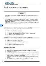
9.5
Alarm Detection Capabilities
77
9
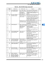
Table 9-5
If the STATUS Orange Lamp Flashes
Alarm
code
Alarm name
Possible cause
Remedy
Sec-
tion
1
78
TMP:VALVE WARN
Cable of water valve is
no connected
correctly.
Confirm the cable from water valve is
surely connected to VALVE connector
of External I/F panel.
4.1
5.3
2
79
EI:DEW WARN
Internal condensation
Check that the ambient temperature
and humidity around the pump and
the temperature of cooling water are
within the specified range.
4.1
5.3
3
80
EI:CONT.TEMP.WARN
Temperature increase
in the control system.
Check that the ambient temperature
around the pump is within the
specified range.
Check that the temperature and flow
rate of the cooling water are within
the specified ranges.
4.1
5.3
4
81
82
83
84
85
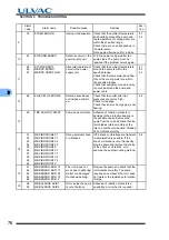
MB:SELFCHECK X1
MB:SELFCHECK Y1
MB:SELFCHECK X2
MB:SELFCHECK Y2
MB:SELFCHECK Z
Rattling of the
protective bearing
becomes pronounced.
Deterioration of the protective bearing
is likely. Overhaul as soon as possible
to avoid damage to the protective
bearing in the event of a power failure
etc.
5
86
87
88
89
90
MB:VIB. WARN. X1
MB:VIB. WARN. Y1
MB:VIB. WARN. X2
MB:VIB. WARN. Y2
MB:VIB. WARN. Z
Transient strong
external shock or
vibrations.
Continuous operation is possible
However, if the shock or vibrations
occur frequently, stop the pump and
remove the source of the shock or
vibrations; or re-examine the pump
mounting method.
5.2
6
91
92
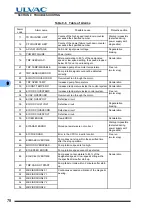
MB:BALANCE WARN.1
MB:BALANCE WARN.2
Rotor inside the pump
is out of balance
Adhesion of reaction products is a
possibility. An overhaul is
recommended.
7
94
MB:AIR RUSH B
Atmospheric
penetration has
occurred.
Create a vacuum system not allowing
atmospheric penetration by
reexamining the operating sequence
of the back pump and valves etc.
8
95
MB:DSP WARNING
Abnormal operation of
circuit in the power
supply unit.
Check that the ambient temperature
around the pump is within the
specified range.
Check that the temperature and flow
rate of the cooling water are within
the specified ranges.
Check that equipment causing noise
is not used around the pump and
power cable.
4.1
5.2
5.3
9
99
MAINTENANCE TIME
Maintenance call timer
has reached the set
time.
Implement maintenance works
prescribed by the customer, such an
overhaul. The alarm can be cancelled
by resetting the maintenance call
timer after implementing necessary
works.
6.6
Содержание UTM2300 Series
Страница 2: ...This page is intentionally left blank...
Страница 10: ...viii Location of Label...
Страница 20: ...6 1 1 2 Descriptions This page is intentionally left blank...
Страница 21: ...2 2IDENTIFICATION AND FUNCTION 2 1 Pump Main Unit 2 2 Control Panel 2 3 External I F Panel...
Страница 25: ...3 3CONSTRUCTION AND PRINCIPLE 3 1 Pump Construction 3 2 Principle of Turbo Molecular Pumping 3 3 Controller...
Страница 30: ...16 3 3 3 Controller This page is intentionally left blank...
Страница 36: ...22 4 4 3 Standards Fulfilled This page is intentionally left blank...
Страница 50: ...36 5 5 5 Notes on Transportation This page is intentionally left blank...
Страница 72: ...58 6 6 8 Communication Specifications This page is intentionally left blank...
Страница 73: ...7 7GAS PURGE...
Страница 82: ...68 8 8 6 Turbo Molecular Pump Return Request This page is intentionally left blank...
Страница 95: ...10 10WARRANTY CLAUSES...
Страница 98: ...84 10 This page is intentionally left blank...
Страница 100: ...Index Index 2 This page is intentionally left blank...

