SECTION 3
CONSTRUCTION AND PRINCIPLE
12
3
3.1
Pump Construction
Fig. 3-1 is a sectional drawing of a magnetic bearing type turbo molecular pump. The built-in
high frequency motor (1) is accelerated to the specified revolutions (speed) by the high frequency
power supply unit. Rotor blades (3) are fitted onto the drive shaft (2) and the stator blades (4) are
arranged in between the rotor blades. A positioning spacer (5) is inserted between the stator
blades. The configurations and profiles of the stator blades and rotor blades are designed for high
efficiencies in various applications. The upper stages of the rotor blade and stator blade
configurations are ideally designed for high gas throughput. The compression ratio of the stator
blades and rotor blades becomes higher as the gas molecules converge into the lower stage
configurations. The profiles of the stator blades and rotor blades are matched for the desired
function.
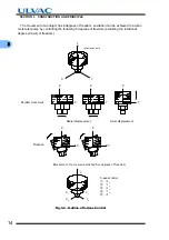
A radial magnetic bearing (6) is used at the top and bottom of the drive shaft. The axial
magnetic bearings (7) are used to levitate a disk attached to the drive shaft between the axial
magnetic bearings. Each magnetic bearing is provided with a gap sensor (9) to detect the rotor
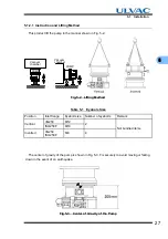
position. Fig. 3-2 illustrates the outline of 5-axes control. The rotor is levitated by the control of
these 5-axes allowing rotational freedom.
A touch-down bearing (8) is used at the top and bottom of the casing for safety protection of
the rotor and pump should the magnetic bearings become damaged. The touchdown bearings
are dry and oil free.
Protective net (12) protects that a foreign object comes in from inlet flange.
The cooling water pipe (13) is provided to cool the pump.
3.2
Principle of Turbo Molecular Pumping
The principle of turbo molecular pumping assumes gas molecules collide with a surface plane
(the blade of the pump rotor) moving in a radial span of very high speed in a space with an
enlarged mean free gas path (generally a vacuum area of less pressure than 0.1 Pa). Assuming
no heat is exchanged between the gas molecule and the pump rotor blade, the speed of the
pump rotor blade is added to the speed of the gas molecule, converting the gas molecule's non-
oriented thermal motion to a motion with direction. Thus the gas molecule has received an
impulse in a desired flow direction.
Содержание UTM2300 Series
Страница 2: ...This page is intentionally left blank...
Страница 10: ...viii Location of Label...
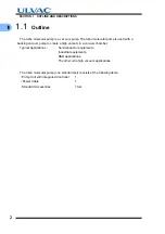
Страница 20: ...6 1 1 2 Descriptions This page is intentionally left blank...
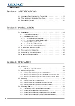
Страница 21: ...2 2IDENTIFICATION AND FUNCTION 2 1 Pump Main Unit 2 2 Control Panel 2 3 External I F Panel...
Страница 25: ...3 3CONSTRUCTION AND PRINCIPLE 3 1 Pump Construction 3 2 Principle of Turbo Molecular Pumping 3 3 Controller...
Страница 30: ...16 3 3 3 Controller This page is intentionally left blank...
Страница 36: ...22 4 4 3 Standards Fulfilled This page is intentionally left blank...
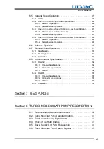
Страница 50: ...36 5 5 5 Notes on Transportation This page is intentionally left blank...
Страница 72: ...58 6 6 8 Communication Specifications This page is intentionally left blank...
Страница 73: ...7 7GAS PURGE...
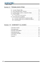
Страница 82: ...68 8 8 6 Turbo Molecular Pump Return Request This page is intentionally left blank...
Страница 95: ...10 10WARRANTY CLAUSES...
Страница 98: ...84 10 This page is intentionally left blank...
Страница 100: ...Index Index 2 This page is intentionally left blank...

