SECTION 2
IDENTIFICATION AND FUNCTION
10
2
2.3
External I/F Panel
Fig.2-3
I/F Panel
(1) REMOTE connector ........................ Connector for remote-control.
(Refer to Section 6.7 "Remote-control Connector".)
(2) SERIAL connector ........................... Connector for RS-232C or RS-485 communication.
(Refer to Section 6.8 "Communication Specifications".)
(3) VALVE connector ............................ Water valve connector.
(Refer to Section 5.3 "Preparation for Operation".)
(Note 1) All interfaces are SELV (safety extra-low voltage).
Содержание UTM2300 Series
Страница 2: ...This page is intentionally left blank...
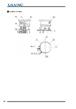
Страница 10: ...viii Location of Label...
Страница 20: ...6 1 1 2 Descriptions This page is intentionally left blank...
Страница 21: ...2 2IDENTIFICATION AND FUNCTION 2 1 Pump Main Unit 2 2 Control Panel 2 3 External I F Panel...
Страница 25: ...3 3CONSTRUCTION AND PRINCIPLE 3 1 Pump Construction 3 2 Principle of Turbo Molecular Pumping 3 3 Controller...
Страница 30: ...16 3 3 3 Controller This page is intentionally left blank...
Страница 36: ...22 4 4 3 Standards Fulfilled This page is intentionally left blank...
Страница 50: ...36 5 5 5 Notes on Transportation This page is intentionally left blank...
Страница 72: ...58 6 6 8 Communication Specifications This page is intentionally left blank...
Страница 73: ...7 7GAS PURGE...
Страница 82: ...68 8 8 6 Turbo Molecular Pump Return Request This page is intentionally left blank...
Страница 95: ...10 10WARRANTY CLAUSES...
Страница 98: ...84 10 This page is intentionally left blank...
Страница 100: ...Index Index 2 This page is intentionally left blank...

