1.61 Prüfung
Gerät ein- und auf „Start" schalten. Rechtes
Kupplungsoberteil festhalten (dabei den
rechten Fühlhebel nicht berühren). Die Frik-
tion zwischen dem linken Friktionsrad, dem
Antriebsrad und der rechten Druckscheibe
muß jetzt so groß sein, daß die rechte Druck-
scheibe mit unverminderter Geschwindigkeit
weiterläuft.
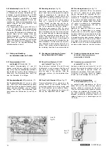
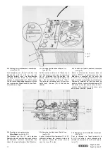
1.62 Einstellung der Betätigungsnase
am Betätigungshebel (siehe Abb. 10)
FunktionswählerüberdieStellung „Start" nach
rechts bis zum Anschlag drehen. In dieser
Stellung muß die Betätigungsnase (R) einen
Abstand von 0,5 ± 0,1 mm zum Lagerarm (S)
aufweisen. Eine gegebenenfalls erforderliche
Einstellung kann durch Biegen der Betäti-
gungsnase (R) erfolgen.
1.7 Prüfung und Einstellung der Bremsen
1.71 Prüfung
. Die Bremsen arbeiten richtungsabhängig und
wirken auf die Druckscheiben der Kupplun-
gen. In Stellung „Start", „Pause" und „Vor-
lauf" muß die rechte, in Stellung „Rücklauf"
muß die linke Bremse abheben. In allen übri-
gen Betriebsstellungen liegen beide Bremsen
an den Druckscheiben an.
1.72 Einstellung (siehe Abb. 10)
Betriebsstellung „Rücklauf" einschalten. Nach
Lockern der Schrauben (O) kann der Betäti-
gungshebel (P) so weit verschoben werden,
daß die linke Bremse (Q) 1,5 mm bis 2 mm
abhebt. /
Die Einstellung der rechten Bremse erfolgt
sinngemäß in Betriebsstellung „Vorlauf".
1.61 Checking
Switch on and set instrument to "Start". Grip
the right-hand upper part of the clutch (do
not touch the right-hand sensing lever while
doing this). Friction between the left-hand
friction pulley, the driving pulley and the
right-hand pressure disk must now be so
great that the right-hand pressure disk con-
tinues to run at undiminished speed.
1.62 Adjusting the Actuating Lug on the
Actuating Lever (see Fig. 10)
Turn the function selector via position "Start"
as far as the end stop in a clockwise direc-
tion. In this position the actuating lug (R)
must have a spacing of 0.5 ± 0.1 mm from
the bearing arm (S). Should an adjustment be
required, it can be effected by bending the
actuating lug (R).
1.7 Checking and Adjusting the Brakes
1.71 Checking
The brakes act on the respective thrust
disks of the clutches and will function only
in one sense of rotation of the latter. When
the function selector is either in its "Start",
"Pause" or "Fast Forward" position, the
right-hand brake must lift; when the function
selector is in its "Rewind" position, the left-
hand brake must lift. During all other set-
tings, both brakes rest against the thrust
disks.
1.72 Adjusting (see Fig. 10)
Set the recorder for rewind operation,
slacken the screws (O) and slide the actua-
tor (P) as far as to lift the left-hand brake
(0) by 1.5-2 millimeters.
The right-hand brake is adjusted in an analo-
gous manner while the recorder is set for
fast forward operation.
1.61 Contrôle
Mettre le sélecteur de fonctions dans sa
position «Start» et immobiliser avec la main
le plateau supérieur de l'embrayage droit
(éviter tout contact avec le levier palpeur
droit). L'effort de friction qui se produit entre
la roue à friction gauche, la roue d'entraîne-
ment et le plateau presseur droit doit être
assez élevé pour que le plateau presseur
droit continue à tourner sans aucune réduc-
tion de sa vitesse. •
1.62 Réglage de l'ergot
du levier d'actionnement (voir fig. 10)
Déplacer le sélecteur de fonctions vers la
droite jusqu'à sa butée, c'est-à-dire au-delà
de la position «Start». L'ergot (R) du levier
d'actionnement doit alors avoir un écart de
0,5 ± 0,1 mm par rapport au bras d'appui (S).
Corriger éventuellement par un cambrage
adéquat de l'ergot (R).
1.7 Contrôle et réglage des freins
1.71 Contrôle
Les freins travaillent en fonction du sens de
défilement de la bande magnétique et agis-
sent sur les plateaux presseurs des embraya-
ges. En régime
«Pause» et «Défile-
ment accéléré avant», le frein droit doit être
dégagé. En régime «Défilement accéléré
arrière», c'est le frein gauche qui doit se
soulever. En régime «Stop», les deux freins
doivent s'appliquer sur les plateaux pres-
seurs.
1.72 Réglage (voir fig. 10)
Enclencher le régime «Défilement accéléré
arrière». Desserrer les vis (O) et déplacer
le levier d'actionnement (P) jusqu'à ce que
le frein gauche (Q) se détache du plateau
presseur sur une distance de 1,5 mm à 2 mm.
Exécuter de façon identique le réglage du
frein droit, mais en régime «Défilement ac-
céléré avant».
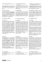
1.8 Austausch der Friktionsräder
und Antriebsriemen
' 1.81 Austausch des linken Friktionsrades
(siehe Abb. 12)
Schraube (R) entfernen, Haltestreifen (S)
ausschwenken, Antriebsriemen (T) aus der
Laufrille des Friktionsrades (D) heben und
Friktionsrad (D) von der Achse abziehen. Der
Einbau ist sinngemäß in umgekehrter Reihen-
folge vorzunehmen. Der Haltestreifen (S)
muß leicht auf das Lager des Friktionsrades
(D) drücken.
1.82 Austausch des rechten Friktionsrades
(siehe Abb. 12)
Nach Entfernen der Seegerringe (U) und Aus-
hängen der Feder (V) wird der Sperrschieber
(K) so weit angehoben und nach rechts be-
wegt, bis sich der Lagerarm (W) mit dem
rechten Friktionsrad (L) herausheben läßt.
Das Friktionsrad (L) kann nach Entfernen des
nunmehr freiliegenden Seegerringes ausge-
tauscht werden. Der Einbau ist sinngemäß in
umgekehrter Reihenfolge vorzunehmen. Es
ist darauf zu achten, daß alle Unterlegschei-
ben wieder eingebaut werden. Das
rad muß ein axiales Spiel von ca. 0,1 mm
aufweisen.
1.8 Replacing the Friction Wheels
and Driving Belts
1.81 Replacing the Left-Hand Friction Wheel
(see Fig. 12)
Remove the screw (R), swing aside the flat
spring (S), remove the driving belt (T) from
the groove of the friction wheel (D) and pull
the friction wheel (D) off its shaft. Install
the new friction wheel in reverse order.
The flat spring (S) must exert a slight force
on the bearing of the friction wheel (D).
1.82 Replacing the Right-Hand Friction Wheel
(see Fig. 12)
Remove the circlips (U) and unhook the
spring (V). Lift the arresting slider (K) and
move it to the right just enough to allow the
mounting arm (W) with the right-hand fric-
tion wheel (L) to be lifted out. Remove the
circlip which is now accessible, and replace
the friction wheel (L). Install the new friction
wheel in reverse order. Take care to replace
all washers. The friction wheel must have an
axial play of approximately 0.1 millimeter.
1.8 Echange des roues à friction
et des courroies
1.81 Echange de la roue à friction gauche
(voir fig. 12)
Dégager la vis (R), détourner la barrette de
retenue (S), sortir la courroie d'entraînement
(T) hors de la gorge de roulement de la roue
à friction (D) et retirer cette roue. Remonter
la nouvelle roue à friction dans l'ordre de
suite inverse. La barrette de retenue (S) doit
presser légèrement sur le palier de la roue
à friction (D).
1.82 Echange de la roue à friction droite
(voir fig. 12)
Retirer les rondelles de sécurité (U) et dé-
crocher le ressort (V). Soulever le curseur de
blocage (K) et le déplacer vers la droite, jus-
qu'à ce que le bras d'appui (W) puisse être
sorti avec la roue à friction (L) droite. La roue
à friction (L) peut être échangée après l'ex-
traction de la rondelle Seeger alors directe-
ment accessible. Remonter la nouvelle roue à
friction dans l'ordre du suite inverse et in-
sérer soigneusement toutes les rondelles
d'épaisseur. La roue à friction doit avoir un
jeu axial d'environ 0,1 mm.
SG 560 Royal


