


51
9.4.2. TCP Setting
TCP offset: When the x/y/z/Roll/Pitch/Yaw value of the TCP offset setting is 0, TCP coincides
with the centre point of the tool output flange.
TCP load and center of gravity: Please set the payload and tool center of gravity offset
according to the actual situation of the arm. The maximum payload does not exceed 5KG. As
the tool's center of gravity shifts, the actual payload will decrease slightly. If there is no
actual load at the end of the arm, the payload must be set to 0.
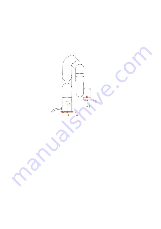
9.4.3.TCP Coordinate System
The TCP coordinate system is defined by the centre point (TCP) of the end of the robotic
arm, and it is the result of rotating [180° , 0° , 0° ] around the x/y/z axis of the base coordinate
system in order. The x/y/z spatial orientation of the TCP coordinate system changes accord-
ing to the changes of the angle of rotation.
Roll /Pitch/Yaw rotates around the X/Y/Z of the TCP coordinate system. The value of ± is the
value of the circle in the range of the rotation angle. The direction of rotation will be rotated
according to the smaller angle between the two points. In particular, it is important to
strictly control the magnitude of the deflection angle between the two points to control the
direction of rotation, and if necessary, insert a third point between the two points. As
shown in figure 6.4, if a deflection is needed from position point A to point B, the robotic
arm moves in the direction of α angle. If the robotic arm needs to be moved in the direction
of β angle, a new position between the angles of β should be inserted, and the angle that
formed by the inserted point and A should be smaller than α.
A:base coordinates
B:TCP coordinates