Doc. 86371S - Rev. 01/02/2021
USER MANUAL
USER MANUAL
EN
EN
Drw. / Dis. 37304
16/43
MANUALE D’ISTRUZIONI
MANUALE D’ISTRUZIONI
IT
IT
8 WIRING
8 COLLEGAMENTI ELETTRICI
B E FO R E P RO C E E D I N G W I T H T H E
MECHANICAL MOUNTING OF THE
ACTUATOR ON THE WINDOW, CARRY
OUT THE WIRING OPERATIONS DESCRIBED
BELOW.
Original spare parts and fittings only shall
be used to install the actuator.
Before carrying out any wiring
operation, disconnect the power
supply.
WARNING
WARNING
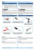
When the chain actuator is not mounted, pay
great attention not to retract the chain into the
actuator completely: the chain could get stuck
irreparably.
WARNING
WARNING
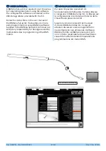
UCS recommends using Dead man push
buttons to control the actuators.
Do not connect power supply to the
feedback signal cables.
WARNING
WARNING
PRIMA DI PROCEDERE CON IL MONTAGGIO
MECCANICO DELL’ATTUATORE SULLA
FINESTRA, EFFETTUARE I COLLEGAMENTI
ELETTRICI DESCRITTI DI SEGUITO.
Installare l’attuatore utilizzando esclusiva
-
mente parti ed accessori originali.
Prima di eseguire qualsiasi operazione,
scollegare l’alimentazione elettrica.
ATTENZIONE
ATTENZIONE
Con il connettore catena non montato, fare estrema
attenzione a non far rientrare completamente la
catena all’interno dell’attuatore, poiché questo
potrebbe causare il blocco irreversibile della
catena stessa.
ATTENZIONE
ATTENZIONE
UCS raccomanda l’uso di pulsanti a uomo
presente per il comando degli attuatori.
Non collegare l’alimentazione sui cavi
del feedback signal.
ATTENZIONE
ATTENZIONE
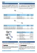
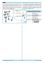
NANO BMS
is provided with two connectors at the
actuator ends. Both the main and the additional
one will need to be used if several actuators (max.
4) are connected.
Il
NANO
BMS
è dotato di due connettori alle
estremità dell’attuatore. Sarà necessario utilizzare
sia quello principale che quello aggiuntivo in caso
di collegamento di più attuatori (max. 4).
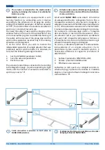
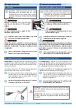
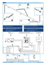
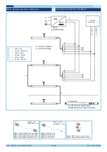
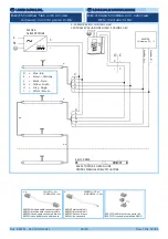
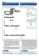
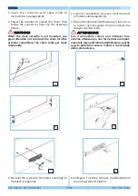
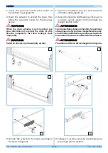
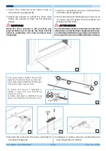
Insert the connector “1” into the proper space on
the actuator and make sure it is locked.
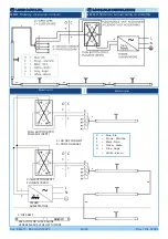
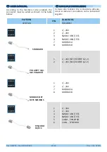
To carry out the main connection, use a
6-pole cable “2”; for the connection between
two actuators, use a 6-pole cable “3” (see
the picture at page 17).
Insert the supplied rubber plug “4” into the
actuator end which is not used.
8.1 Cable connection
8.1 Collegamento cavi
Inserire il connettore “1” nell’apposito alloggiamento
dell’attuatore e verificarne il bloccaggio.
Per il collegamento principale, utilizzare un
cavo 6 poli “2”; per il collegamento tra due
attuatori, utilizzare un cavo 6 poli “3” (vedi
figura a pagina 17).
Inserire il tappo di gomma “4” nell’estremità
dell’attuatore non utilizzata.
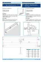
WARNING: In order to remove the connector, DO NOT
PULL THE CABLE; release the special wings by using
two screwdrivers.
ATTENZIONE: Per estrarre il connettore, NON TIRARE
IL CAVO; sganciare le apposite alette utilizzando due
cacciaviti.


