background image

9

Chapter 2: Installation

airFiber

®

 AF5/AF5U User Guide

 Ubiquiti Networks, Inc.

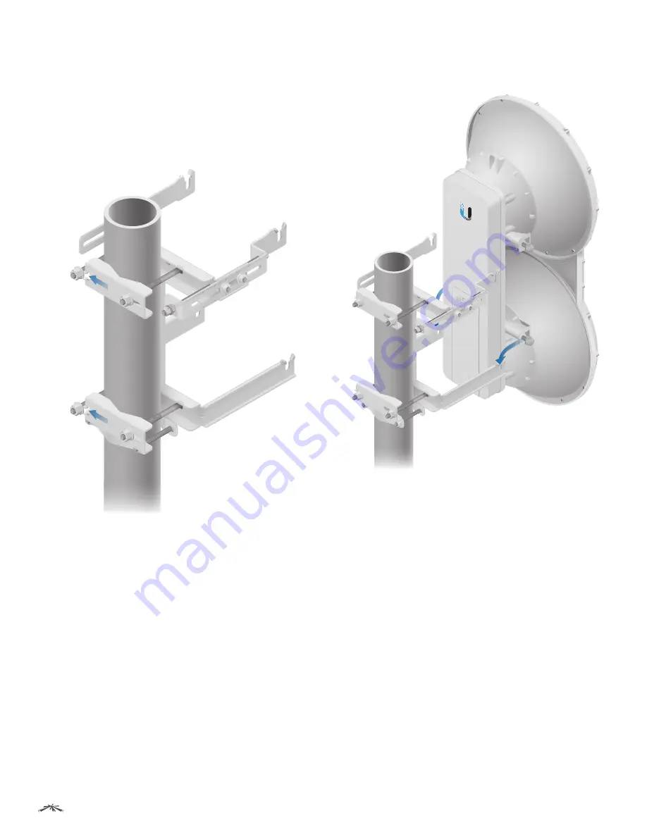
2.  Attach the mounting assembly to a pole.
a.  Orient the mounting assembly around the pole so it is 

aimed in the direction of the other airFiber radio. 

b.  Slide the open slot of each 

Pole Clamp

 over the 

corresponding 

M10x150 Carriage Bolt.

c.  Tighten the 

M10 Serrated Flange Nuts 

of the 

M10x150 

Carriage Bolts 

to secure the mounting assembly to the 

pole.

3.  Lift the airFiber radio and align the two lower 

Pre-Installed M10x25 Flanged Bolts

 with the slots on the 

Lower Mount Bracket

. Seat the bolts in the slots.

Содержание airFiber 5

Страница 1: ...5 GHz Full Duplex Point to Point Gigabit Radio Models AF 5 AF 5U...

Страница 2: ...wer over Ethernet 4 airFiber Configuration 5 Hardware Installation 7 Connecting Ethernet 10 Alignment 12 Chapter 3 Navigation 18 Accessing the airFiber Configuration Interface 18 Product Verification...

Страница 3: ...t 37 Chapter 10 Tools 38 Align Antenna 38 Discovery 39 Ping 39 Traceroute 39 Appendix A Specifications 40 Appendix B Safety Notices 42 Electrical Safety Information 42 Appendix C Warranty 43 Limited W...

Страница 4: ...encies which are freely used in many parts of the world The high band model AF 5U which can operate in the 5 7 6 2 GHz bands has robust filtering to enable co location with devices operating in the lo...

Страница 5: ...Synchronization On Operational Strong Signal Normal Flash Non Operational Weak Signal Master Off Slave mode On Master mode Link Status Off RF Off Short Flash Syncing DFS countries only DFS CAC RADAR...

Страница 6: ...radios must use the same Wireless Mode Master or Slave Back to back airFiber radios can use the same frequency We recommend that you use different frequencies for adjacent airFiber radios however thi...

Страница 7: ...Pre assemble the mounting hardware Install the airFiber radios at the site Establish and optimize the RF link Note The AF 5 and AF 5U models share the same installation and configuration instructions...

Страница 8: ...on the Slave and vice versa 1 Connect an Ethernet cable from your computer to the Management port on the airFiber radio GPS MASTER LINK RESET OVERLOAD 8X 6X 4X to 0 25X REMOTE LOCAL AUX MANAGEMENT DA...

Страница 9: ...X or ASCII b For the Key field HEX Enter 16 bytes eight 16 bit HEX values 0 9 A F or a f You can omit zeroes and use colons similar to the IPv6 format Note The airFiber Configuration Interface support...

Страница 10: ...two M10x150 Carriage Bolts into the Upper Mount Bracket with Elevation Rod 3 Attach the Lower Mount Bracket to the I Bracket using two M8x14 Serrated Flange Bolts Ensure that the slots face up and sec...

Страница 11: ...rriage Bolt c Place one M10 Serrated Flange Nut on each M10x100 Carriage Bolt 7 Ensure that there is a 13 mm gap between the head of each Pre Installed M10x25 Flanged Bolt and the corresponding trunni...

Страница 12: ...ection of the other airFiber radio b Slide the open slot of each Pole Clamp over the corresponding M10x150 Carriage Bolt c Tighten the M10 Serrated Flange Nuts of the M10x150 Carriage Bolts to secure...

Страница 13: ...perly ground your airFiber units will void your warranty Note The ground wire should be as short as possible and no longer than one meter in length Connecting Ethernet 1 Push the button and slide the...

Страница 14: ...ther end of the Power Cord to a power source Note For added protection we recommend installing two GigE PoE surge protectors Install the first surge protector within one meter of the airFiber Data por...

Страница 15: ...ne on page 16 Using the LED Displays Before a link is established the Master s LED Display looks like this GPS and Master LEDs are solidly lit Note The GPS LED may not be lit if there is a weak GPS si...

Страница 16: ...ays are displayed in negative dBm For example 67 represents a received signal level of 67 dBm Smaller numerical values indicate stronger received signal levels For example a reading of 49 is stronger...

Страница 17: ...o point and optimize the antenna in the direction of maximum link signal The Antenna Alignment window is designed to refresh every 250 milliseconds See Align Antenna on page 38 for more details 7 The...

Страница 18: ...Smaller numerical values indicate stronger received signal levels For example a reading of 49 dBm is stronger than a reading of 55 dBm Note Maximum signal strength can best be achieved by iteratively...

Страница 19: ...of the mono jack RJ 12 Connector Return Shield Left Right Channel Wire to Pin 6 Wire to Pin 5 Pin Audio Jack 6 5 4 3 2 1 Pinouts from RJ 12 to 3 5 mm Stereo Phono Jack Note Wire colors may vary on RJ...

Страница 20: ...signal level on the Master Note If the Overload LED lights up identify and eliminate any source of strong in band interference 7 Repeat steps 6 and 7 until you achieve a symmetric link with the signal...

Страница 21: ...t Network Settings on page 26 for more details Accessing the airFiber Configuration Interface Connect to the airFiber Configuration Interface 1 Make sure that your host machine is connected to the LAN...

Страница 22: ...20 displays device status statistics and network monitoring links Wireless The Wireless Tab on page 23 configures basic wireless settings including the wireless mode link name frequency output power s...

Страница 23: ...egistration screens and discovery tools Operating Mode Displays the mode of the airFiber AF 5 Slave Master or Reset RF Link Status Displays the status of the airFiber AF 5 RF Off Syncing Beaconing Reg...

Страница 24: ...played in YEAR MONTH DAY HOURS MINUTES SECONDS format The system date and time is retrieved from the Internet using NTP Network Time Protocol The NTP Client is enabled by default on the Services tab T...

Страница 25: ...GPS tracking reports the device s current altitude relative to sea level Synchronization airFiber uses GPS to synchronize the timing of its transmissions By default this option is disabled Monitor The...

Страница 26: ...y within 180 seconds the countdown is displayed the airFiber AF 5 times out and resumes its earlier configuration Discard To cancel your changes click Discard Write down the settings you configure on...

Страница 27: ...new country click Change Note U S product versions are locked to the U S Country Code to ensure compliance with FCC regulations Country Select the new country I agree to these terms of use Check this...

Страница 28: ...frequencies as fallback options in case of a radar induced shutdown For example if radar is detected on TX Frequency 1 then the airFiber radio will switch to TX Frequency 2 The three TX Frequencies o...

Страница 29: ...work Settings In Band Management Enabled by default In band management is available through the local Data port or the Data port at the other end of the link Note If In Band Management is enabled ensu...

Страница 30: ...he IP address of the primary DNS Domain Name System server Secondary DNS IP Specify the IP address of the secondary DNS server This entry is optional and used only if the primary DNS server is not res...

Страница 31: ...s transmissions By default this option is disabled DATA Port Ethernet Settings DATA Speed This is the speed of the Data port By default the option is Auto The airFiber AF 5 automatically negotiates tr...

Страница 32: ...y if the RF link is still down The Ethernet link s uptime is long enough so the operator has enough time to access the airFiber AF 5 make configuration changes and save those changes Sufficient Ethern...

Страница 33: ...ort s Ethernet link follows the RF link state exactly If the RF link goes down then the Ethernet link goes down and remains down until the RF link goes back up MGMT Port Ethernet Settings MGMT Speed T...

Страница 34: ...untdown is displayed the airFiber AF 5 times out and resumes its earlier configuration Discard To cancel your changes click Discard Ping Watchdog Ping Watchdog sets the airFiber AF 5 to continuously p...

Страница 35: ...etwork provisioning Allows network administrators to monitor network performance and troubleshoot network problems For the purpose of equipment identification configure the SNMP Agent with contact and...

Страница 36: ...erver NTP Client Network Time Protocol NTP is a protocol for synchronizing the clocks of computer systems over packet switched variable latency data networks You can use it to set the system time on t...

Страница 37: ...e commonly used system message logging utilities Every logged message contains at least a system time and host name Usually a specific service name that generates the system event is also specified wi...

Страница 38: ...y To immediately save your changes click Apply Test To try the changes without saving them click Test To keep the changes click Apply If you do not click Apply within 180 seconds the countdown is disp...

Страница 39: ...you to select the language displayed in the web management interface English is the default language Date Settings Time Zone Specifies the time zone in relation to Greenwich Mean Time GMT Startup Dat...

Страница 40: ...This generates a support information file that the Ubiquiti support engineers can use when providing customer support This file only needs to be generated at their request Configuration Management The...

Страница 41: ...ry 250 milliseconds Chain 0 1 Signal Strength Displays the absolute power level in dBm of the received signal for each chain Note If Overload is displayed to indicate an overload condition identify an...

Страница 42: ...work Ping Select Destination IP You have two options Select a remote system IP from the drop down list which is generated automatically Select specify manually and enter the IP address in the field di...

Страница 43: ...Kit Included Wind Loading 863 N 200 km hr 194 lbf 125 mph Wind Survivability 200 km hr 125 mph Operating Temperature 40 to 55 C 40 to 131 F LEDs 12 Status LEDs Data Port Link Activity Data Port Speed...

Страница 44: ...Mbps 128 Mbps 1x Rate QPSK xRT 93 dBm 90 dBm 88 dBm 87 dBm 128 Mbps 64 Mbps x Rate QPSK xRT 95 dBm 93 dBm 92 dBm 91 dBm 32 Mbps 16 Mbps FDD 2 50 MHz channels and TDD 1 50 MHz channel xtreme Range Tech...

Страница 45: ...rts inside this equipment Service should be provided only by a qualified service technician 3 This equipment is provided with a detachable power cord which has an integral safety ground wire intended...

Страница 46: ...cessed and will be returned freight collect or subject to disposal Information on the RMA process and obtaining an RMA number can be found at www ubnt com support warranty Disclaimer EXCEPT FOR ANY EX...

Страница 47: ...states and provinces do not allow the exclusion or limitation of liability for incidental or consequential damages so the above limitation may not apply to you EXCEPT TO THE EXTENT ALLOWED BY LOCAL LA...

Страница 48: ...o the following two conditions 1 This device may not cause interference and 2 This device must accept any interference including interference that may cause undesired operation of the device CAN ICES...

Страница 49: ...70 5725 30 5755 5875 36 Greece AF5 AF5U 5470 5725 30 5725 5795 36 Grenada AF5 AF5U 5470 5725 30 5725 5850 36 Guatemala AF5U 5735 5835 30 Honduras AF5 AF5U 5470 5725 30 5725 5850 36 Hong Kong AF5 AF5U...

Страница 50: ...Portugal AF5 AF5U 5470 5725 30 5725 5875 36 Puerto Rico U S territory AF5 AF5U 5470 5600 5650 5725 30 5725 5850 50 Qatar AF5U 5735 5835 30 Russia AF5 AF5U 5470 5725 23 5725 5850 23 Singapore AF5U 573...

Страница 51: ...ratos el ctricos y electr nicos a trav s de los puntos de recogida que ponen a su disposici n el gobierno y las autoridades locales Al desechar y reciclar correctamente estos aparatos estar contribuye...

Страница 52: ...linie 1999 5 EG Wien Greek UBIQUITI NETWORKS UBIQUITI NETWORKS device 1995 5 Magyar Hungarian Alul rott UBIQUITI NETWORKS nyilatkozom hogy a UBIQUITI NETWORKS device megfelel a vonatkoz alapvet k vete...

Страница 53: ...spond to support inquiries within a 24 hour period Online Resources Support support ubnt com Community community ubnt com Downloads downloads ubnt com 2580 Orchard Parkway San Jose CA 95131 www ubnt c...

Отзывы: