background image

http://www.tyan.com

3-2

Chapter 3

BIOS Configuration

You can select a Setup option by using the following keyboard keys:

The pages which follow contain explanations of the settings for the AMIBIOS
Setup menus.  Drawings have been included for ease of reference.  Overall, the
AMIBIOS Setup program is easy to use, and fairly intuitive. Note that the
graphics in the manual are simpler than those that appear on your screen.

3.1 Main Setup

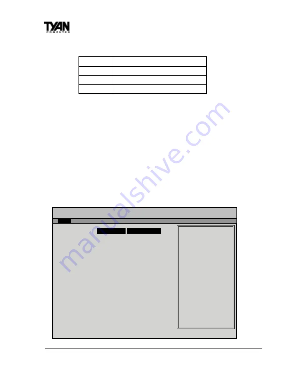
Select the AMIBIOS Setup options below by choosing Main Setup from the
AMIBIOS Setup main menu. The Standard Setup menu screen is shown below.

Key

Function

Tab

Moves from one box to the next

Arrow keys Changes selections within a box

Enter

Opens highlighted selection

                        AMI BIOS EASY SETUP UTILITY Ver.1.16

               (c)1998 American Megatrends, Inc.  All Rights Reserved


   Main    Advanced    Security    Exit


System Date

Fri Jan 1 1999

       Setup Help

                      System Time

12:55:37

  Month:

 Jan - Dec

                   Floppy Drive A

1.44 MB 3½

    Day:

  01 - 31

                   Floppy Drive B

Not Installed

   Year:

1901 - 2099

               Primary IDE Master

Auto

                Primary IDE Slave

Auto

             Secondary IDE Master

Auto

              Secondary IDE Slave

Auto

           Auto-Detect Hard Disks

[ Enter ]

     Boot Sector Virus Protection

Disabled

↑ 

Previous Item

 Next Item

Select Menu

   ESC:Exit  Enter:Select  F5:Setup Defaults  F6:Original Values  F10:Save & Exit

Содержание THUNDER X

Страница 1: ... Megatrend Incorporated Windows is a trademark of Microsoft Corporation IBM PC AT PS 2 are trademarks of IBM Corporation INTEL Pentium II Celeron Xeon are trademarks of Intel Corporation S1952 Thunder X is a trademark of TYAN Computer Corporation Information contained in this publication has been carefully checked for accuracy and reliability In no event will Tyan Computer be held liable for any d...

Страница 2: ...nstallation 2 10 Hardware Reset Switch Connector Installation 2 10 ExternalSMI 2 10 Chassis IntrusionAlarm Connector 2 11 CMOSRTC 2 11 FlashEEPROM 2 11 MemoryInstallation 2 12 CacheMemory 2 15 CPUInstallation 2 15 Add on Card Installation 2 21 Power Supply Installation 2 22 Connecting IDE SCSI Cables and Devices 2 23 Connecting Floppy Drives 2 24 Connecting Com and Printer Ports 2 25 Connecting US...

Страница 3: ...Questions A 1 Boot Issues A 1 VideoIssues A 3 CPUIssues A 4 Memory Issues A 5 Hard Drive Floppy Drive Issues A 6 BIOSIssues A 7 DriverIssues A 8 Miscellaneous Issues A 8 AppendixB AdaptecUltra2LVDSCSI B 1 Introduction B 1 SettingUpSCSIPeripherals B 3 ConnectingSCSIPeripherals B 4 AdditionalTermination Information B 7 InstallingAIC7896SCSISoftware B 8 Troubleshooting B 9 AppendixC Glossary C 1 ...

Страница 4: ...lications such as CAD CAM CAE desktop publish ing 3D animation and video production This integrated system board achieves high reliability with numerous features and yet is small enough to be supported in an extended ATX form factor Some of the features included are onboard dual channel PCI PIO Bus Master IDE and UltraDMA 33 onboard floppy controller onboard 32 bit PCI Ultra2 dual channel SCSI and...

Страница 5: ...d always read every word in the text Failing to do so can lead to exasperation and expense Wherever possible we have included step by step instructions for setting up your system which are indicated by this icon However it is in your best interest to read an entire section and perhaps the entire manual before you begin to fiddle with your motherboard While we have alerted you to potential dangers ...

Страница 6: ...n 12V power source for DC fan onboard 3 3V DRAM support Utilizes GTL bus to reduce power consumption and EMI MainMemory Up to 2 GB memory support Four 168 pin DIMM sockets Supports SDRAM w SPD SDRAM ECC 100MHz SDRAM support SystemManagement ADM9240 sensor chip with onboard alarm for heat fan and voltage Intel LANDesk Client Manager software included Chassis intrusion detection capable Power recove...

Страница 7: ...hield BIOSInformation AMI Plug and Play flash BIOS Deep Green Energy Star ACPI Year 2000 and PC98 compliant Soft power down multiple boot options Win98 NT5 ready DMI 2 0 compliant PCI 2 1 APM 1 1 compliant Disk Drive System I O Two PCI bus mastering EIDE channels Supports EIDE CD ROMs PIO Mode 3 4 up to 17MB sec DTR Support for two floppy drives up to 2 88MB TwoATX serial ports 16550 UARTs OneATX ...

Страница 8: ...hey should be of the most assistance Further if you purchased your system from a dealer near to you you can actually bring your system in to them to have it serviced instead of attempting to do so yourself which can have expensive consequences Please keep in mind that due to the volumes of emails and technical support calls we receive our response time may not necessarily be immediate If your deal...

Страница 9: ...abuse or improper maintenance of products For Resellers Only A receipt or copy of your invoice marked with the date of purchase is required before any warranty service can be rendered You can obtain service by calling the manufacturer for a Return MerchandiseAuthorization RMA number The RMA number should be prominently displayed on the outside of the shipping carton and the package should be maile...

Страница 10: ...http www tyan com 1 10 Chapter 1 Introduction This page has been intentionally left blank ...

Страница 11: ...ble pack 1 One Ultra 2 LVD 68 pin SCSI cable 1 One 50 pin SCSI cable 1 S1952 User s Manual 1 One CPU retention module set 1 System Management Driver CD Intel LANDesk 2 2 Installation You are now ready to install your motherboard The mounting hole pattern of the S1952DLU matches the ATX system board specifications Your chassis should be that of an extended ATX mainboard form factor ...

Страница 12: ...esandchips 5 Place motherboard on a grounded antistatic surface or on the antistatic bag Having reviewed the precautions above the next step is to take the mother board out of the cardboard box and static bag hold it by its edges and place it on a grounded antistatic surface component side up Inspect the board for damage DONOTAPPLYPOWERTOTHEBOARDIFITHASBEENDAMAGED Press down on any of the socket I...

Страница 13: ...l rod inside the plastic shell bridges the gap between the two pins completing the circuit See Figure 2 2 for more example of pin connections Quick References for Jumpers The tables and maps on the following pages will help you set the jumpers for CPU speed Infrared and external connector pin assignments among others The miniature motherboard maps will help you locate the jumpers on your board A f...

Страница 14: ... 1 DIMM bank 2 DIMM bank 3 DIMM bank 4 Intel 82443GX 3V Lithium Battery Intel 82371EB Adaptec AIC 7896N CPU 2 Slot 2 Type CPU 1 Slot 2 Type FAN3 FAN2 FAN6 Floppy Drive Secondary IDE Primary IDE Ultra 2 SCSI Ch A Ultra 2 SCSI Ch B SCSI SE JP15 JP19 1 1 1 1 1 1 1 1 1 1 1 JP21 FAN4 1 JP35 1 1 JP27 1 J8 J17 JP36 JP3 JP11 JP12 JP13 JP14 I O APIC I O Chip JP28 1 1 2 JP20 J14 J15 JP23 JP22 JP17 J13 J18 J...

Страница 15: ...tec AIC 7896N Intel 82371EB PIIX4e 1 ISA Slot 6 PCI slots COM2 L P T 1 COM1 USB ports PS 2 ports Slot2 slots Intel 82443GX 4 DIMM slots AMIBIOS AGP port I O APIC IDE and Floppy connectors 2 Ultra2 LVD SCSI channels 1 Narrow SCSI channel ...

Страница 16: ...MOS Clear Jumper JP3 Hardware CMOS Password Reset If you have been locked out of your system because you forgot your password or set the CMOS incorrectly follow the instructions below 1 Power off the system and unplug your power supply 2 Set jumper JP3 to pins 2 and 3 see next page for location of JP3 3 Wait for 2 seconds then return jumper JP3 to pins 1 and 2 4 Power on the system again plug in y...

Страница 17: ... 7 or 7 8 6 8 or 5 6 9 15 Functions HD LED Power LED Reset Switch Power On Off Infra Red Assignment 1 LED 3 LED 5 GND 7 Reset 8 GND 5 GND 6 Power 8 GND 9 VCC 11 IR RX 13 GND 15 IR TX 1 2 3 4 5 6 7 8 9 0 1 1 1 2 1 3 1 4 1 5 1 6 1 7 1 8 1 Top Bottom Top Pin Bottom Pin J10 Side View JP20 Pin1 Pin17 Pin2 VC C 1 2 P o wer LED H D D LED 3 4 Sleep LED G ro und 5 6 P o wer O n O ff R es et 7 8 G ro und VC...

Страница 18: ...t Jumper JP28 8 Wake On LAN Jumper JP15 9 Wake On Ring Jumper JP19 E xternal Spkr Internal B uzzer D efault JP 35 1 4 3 4 1 VC C 2 LED 3 LED 4 VC C Enable SCSI Disable SCSI JP 36 OFF ON N M SM B C LK 2 1 SER VER SM I GN D 4 3 GN D M N SM B D A T A 6 5 ON OF F in KEYUN LK 8 7 LP OK N M SB 3V 10 9 N M IOUT GN D 12 11 F P _R SET N o C o nnect 14 13 GN D GN D 16 15 SEC UR E N o C o nnect 18 17 C H ISI...

Страница 19: ...by 5V GND Wake Pw r ON Active High FAN 1 6 GND VCC Fan Monitor Speed Detect Fan1 CPU2 D etec t 0 Fan2 CPU1 D etect 1 Fan3 Chassis N o Speed D etec t Fan4 Chassis N o Speed D etec t Fan5 CPU2 N o Speed D etec t Fan6 CPU1 N o Speed D etec t JP35 JP21 JP27 JP36 JP15 JP19 JP28 FAN4 FAN3 FAN1 FAN2 FAN5 FAN 6 ...

Страница 20: ...e power button once will wake the system or send it to Suspend mode In this case you cannot turn the system off unless you shut down through the Windows operating system or you hold the power button down for four seconds Speaker Connector Installation The Thunder X provides a 4 pin header to connect the external speaker The speaker should be connected to pins 1 4 of jumper JP35 As default pins 3 4...

Страница 21: ...C circuit which provides the date and time for the system If the external battery for the RTC is low it will prevent your system from POSTing and you will not get a display Normally the life span of an external battery is 2 years If yours is running low you will need to replace it with a new 3V lithium battery Sony CR2032 Flash EEPROM The Thunder 100 uses flash memory to store BIOS programs It can...

Страница 22: ...rd Many of our competitors do not adhere to the strict tolerances required for high performance If you buy a TYAN board you are getting the best system available To make installation easy and trouble free get high quality parts Some brands we recommend are Advantage Memory Corsair Microsystems Millennium Kingston Memory QesTec Incorporated Unigen Micron Tech nology and Crucial Technology These DIM...

Страница 23: ...module Figure 2 4 Place the DIMMs in an antistatic bag as soon as you remove them to avoid static damage The Thunder X uses a 64 bit data path from memory to CPU and can accom modate up to 1024MB of SDRAM 2GB of SDRAM has not been validated The 168 pin DIMMs Dual In line Memory Modules must be of the 3 3V unbuffered variety The position of the notch in the SDRAM key position will tell you whether ...

Страница 24: ...MM 2 DIMM 3 DIMM 4 Total Memory 8MBx1 0 0 0 8MB 8MBx1 8MBx1 0 0 16MB 8MBx1 8MBx1 8MBx1 0 24MB 16MBx1 8MBx1 8MBx1 0 32MB 16MBx1 16MBx1 8MBx1 8MBx1 48MB 16MBx1 16MBx1 16MBx1 0 48MB 32MBx1 16MBx1 16MBx1 0 64MB 32MBx1 32MBx1 16MBx1 16MBx1 96MB 32MBx1 32MBx1 32MBx1 32MBx1 128MB 64MBx1 32MBx1 32MBx1 0 128MB 64MBx1 64MBx1 32MBx1 0 160MB 64MBx1 64MBx1 64MBx1 0 192MB 128MBx1 64MBx1 64MBx1 0 256MB 128MBx1 1...

Страница 25: ... fingers Before the CPU is installed the motherboard must be placed on a flat surface You should be able to insert the CPU with minimal but firm pressure Do not press down hard on the CPU Currently Intel produces two types of Pentium II processors the active or boxed cooling processor and the passive cooling processor see Figure 2 6 below These two types of processors are essentially the same in d...

Страница 26: ...the mounting holes should be used for the plastic standoffs If your case does not have a hole for a standoff simply cut off the bottom of the plastic standoff so that the flat portion rests on the metal The adapter cards and the screws holding them down will keep your board flat The fastening screw should not short any of the traces on the motherboard Make certain that you do not overtighten the s...

Страница 27: ...ine up the pins on the bottom of the brace with the retention brace holes At the same time make sure the chassis bolts are in line with the bolt holes on the retention brace There is only one correct orientation for the modules to be set properly Set the braces in place and fasten them to the bolt using a nut Tighten the nut in a clockwise manner to secure the brace to the board Warning Do NOT ove...

Страница 28: ...e the alignment of the CPUs with each slot and fasten on top of the retention brace to lock the CPUs in place On each side of the handle is a small hook that fits nicely into the notches on the sides of the CPU See Figure 2 11 In or der to attach the handle slide the handle over the top side of the CPU until the handle snaps into place See Figure 2 12 Figure 2 10 Figure 2 11 hook Figure 2 12 ...

Страница 29: ...de of the cooling fan or heat sink See Figure 2 13 When the handle is securely installed you are ready to plug in the CPU Slide the CPU between the two retention braces and onto CPU1 slot Make sure that the fan or heat sink is facing away from the edge of the motherboard Press down firmly on the handle until the CPU is securely in the slot see Figure 2 14 below Be sure to screw the handles onto th...

Страница 30: ...n or heat sink is facing away from the edge of the motherboard see Figure 2 14 on previous page If you have an active cooling processor you will need to connect the CPU s fan cable to the fan power connector on the board Locate the fan connector e g FAN1 on the motherboard Plug the CPU s fan cable into the fan connector There will be a plastic clip assembly similar to that of the ATX power connect...

Страница 31: ...look at the socket on the computer to make sure there are no wires or other obstructions to the slot NEVER plug an ISA card into a PCI slot or a PCI card in an ISA slot You will void your warranty and damage your system board if you do this When plugging the card in especially when installing long cards try to push the entire card in at one time Don t force one end of the card into the socket firs...

Страница 32: ...ay have in your system Figure 2 17 shows an ATX power connector When plugging in the power connector make sure that the plastic clip on the power connector is aligned with the plastic tab on the onboard connector see Figure 2 18below Make certain that you do not miss any pins because if you do you will void your warranty and cause damage to yourself or your motherboard when you turn the system on ...

Страница 33: ...rd drive Notice how Pin 1 denoted by a red stripe is connected so that it is next to the power connector of the drive In most cases this is the proper way of connecting your IDE cable to the hard drive Figure 2 20 shows the IDE cable properly connected to the motherboard The Thunder X motherboard is equipped with three onboard SCSI connectors two Ultra 2 SCSI channels and one Single Ended SCSI cha...

Страница 34: ... cable is on backwards Hard drive lights are constantly on bad IDE cable or defective drives motherboard Try another HDD Hard drives do not power up check power cables and cabling May also be a bad power supply or IDE drive 2 9 Connecting Floppy Drives Pin 1 on the floppy cable is usually denoted by a red or colored stripe down one side of the cable see Figure 2 21 below Most of the current floppy...

Страница 35: ...nother single floppy drive to verify the problem or try another cable Also check to see if the onboard floppy is enabled in the BIOS Floppy Drive Fail message at bootup the cable floppy or motherboard may be faulty Try another cable or floppy drive to verify Light on the floppy is on constantly a dead giveaway that the cable is on backwards Reverse the cable at the motherboard end and try again 2 ...

Страница 36: ... PS 2 keyboard port is the lower PS 2 port The PS 2 connectors are probably quite familiar to you The USB connectors however may be foreign The USB Universal Serial Bus is a versatile port This one port type can function as a serial parallel mouse keyboard or joystick port It is fast enough to support video transfer and is capable of supporting up to 127 daisy chained peripheral devices Figure 2 2...

Страница 37: ... may sound difficult but by following these directions you should have a fairly uneventful time installing our products If you do encounter problems your dealer will be able to help you or you can consult one of our many technical support resources see page 1 8 Figure 2 23 ...

Страница 38: ...http www tyan com 2 28 Chapter 2 Board Installation This page has been intentionally left blank ...

Страница 39: ... Date Thu Oct 15 1998 Setup Help System Time 12 55 37 Month Jan Dec Floppy Drive A 1 44 MB 3 Day 01 31 Floppy Drive B Not Installed Year 1901 2099 Primary IDE Master Auto Primary IDE Slave Auto Secondary IDE Master Auto Secondary IDE Slave Auto Auto Detect Hard Disks Enter Boot Sector Virus Protection Disabled Previous Item Next Item Select Menu ESC Exit Enter Select F5 Setup Defaults F6 Original ...

Страница 40: ...n menu The Standard Setup menu screen is shown below Key Function Tab Moves fromone boxto the next Arrow keys Changes selections within a box Enter Opens highlighted selection AMI BIOS EASY SETUP UTILITY Ver 1 16 c 1998 American Megatrends Inc All Rights Reserved Main Advanced Security Exit System Date Fri Jan 1 1999 Setup Help System Time 12 55 37 Month Jan Dec Floppy Drive A 1 44 MB 3 Day 01 31 ...

Страница 41: ...econdary Slave Select these options to configure the various drives A screen with a list of drive parameters appears System Date Setting MM DD YY Jan 1 1998 System Time Setting Current Time 12 00 00 OPTIONS Not Installed 360 KB 5 1 2 MB 5 720 KB 3 1 44MB 3 2 88MB 3 AMI BIOS EASY SETUP UTILITY Ver 1 16 c 1998 American Megatrends Inc All Rights Reserved Main IDE Device Configuration AUTO Setup Help ...

Страница 42: ...e v i r d e h t f i B M 0 4 5 t c e l e S e d o M k c o l B t c e l e S n O s r e f s n a r t a t a d e d o m k c o l b w o l l a o t t c e l e S e d o M t i B 2 3 t c e l e S n O t c e l e S s r e f s n a r t a t a d t i b 2 3 w o l l a o t e h t e d o M O I P t c e l e s o t t s e b s i t I o t u A o t S O I B I M A w o l l a o t t o n s i t a h t e d o m O I P a t c e l e s u o y f I e d o m O ...

Страница 43: ...e p m o c e r P e t i r W P W k c a r t e h t s a r e l l a m s y l e v i s s e r g o r p s t e g r o t c e s a f o e z i s l a c i s y h p l a u t c a e h T e t i r W s e t y b 2 1 5 d l o h l l i t s t s u m r o t c e s h c a e t e Y s e h s i n i m i d r e t e m a i d l a c i s y h p e h t r o f s e t a s n e p m o c k s i d d r a h e h t n o y r t i u c r i c n o i t a s n e p m o c e r p r e ...

Страница 44: ...aults The Optimal default values provide optimum performance settings for all devices and system features Fail Safe Defaults The Fail Safe default settings consist of the safest set of parameters Use them if the system is behaving erratically They should always work but do not provide optimal system performance characteristics AMI BIOS EASY SETUP UTILITY Ver 1 16 c 1998 American Megatrends Inc All...

Страница 45: ... Em ulated as A uto A uto 1st B o o t D evice F lo ppy F lo ppy 2nd B o o t D evice 1st ID E H D D 1st ID E H D D 3rd B o o t D evic e A T A P I C D R OM A T A P I C D R OM T ry Other B o o t D evices Yes Yes F lo ppy A cc ess C o ntro l R ead Write R ead Write H ard D isk A c cess C o ntro l R ead Write R ead Write AMI BIOS EASY SETUP UTILITY Ver 1 16 c 1998 American Megatrends Inc All Rights Res...

Страница 46: ... o n s e o d S O I B I M A t o n s e o d S O I B I M A e v i r d t a h t e r u g i f n o c t o n s e o d S O I B I M A e v i r d E D I e h t m o r f y l e t a i d e m m i d e v i e c e r t o n s i n i a g a y d a e r t e g o t e m i t e v i r d E D I e h t w o l l a o t e v i r d E D I e h t o t l a n g i s T E S E R a g n i d n e s r e t f a s d n o c e s 5 r o f t i a w e h t r o f y a l e d o n...

Страница 47: ... The settings areDisabled 1st IDE HDD 2ndIDE HDD 3rd IDE HDD 4thIDE HDD Floppy ARMD FDD ARMD HDD ATAPI CDROM and SCSI 3rdBootDevice This option sets the type of device for the third boot drive that the AMIBIOS attempts to boot from after AMIBIOS POST completes The settings are Disabled 1st IDE HDD 2nd IDE HDD 3rd IDE HDD 4th IDE HDD Floppy ARMD FDD ARMD HDD ATAPICDROM Try OtherBoot Devices Set thi...

Страница 48: ...gs areAbsent VGA EGA CGA40x25 CGA80x25 or Mono Password Check This option enables password checking every time the system boots or when you run AMIBIOS Setup If Always is chosen a user password prompt appears every time the computer is turned on If Setup is chosen the pass word prompt appears ifAMIBIOS is executed Boot To OS 2 Set this option to Yes if you are running an OS 2 operating system and ...

Страница 49: ... n i t t e S n o i t p i r c s e D d e l b a s i D M A R o t d e i p o c t o n e r a M O R o e d i v e h t f o s t n e t n o c e h T d e l b a n E o t M O R m o r f d e w o d a h s d e i p o c e r a h F F F 7 C h 0 0 0 C m o r f a e r a M O R o e d i v e h t f o s t n e t n o c e h T n o i t u c e x e r e t s a f r o f M A R d e h c a C n a c d n a M A R o t M O R m o r f d e i p o c e r a h F F F...

Страница 50: ...ed Chipset setup Plug and Play Setup Enter for configuring Peripheral Setup Enter chipset features Change Language Setting Engish Previous Item Next Item Select Menu ESC Exit Enter Select F5 Setup Defaults F6 Original Values F10 Save Exit Setting Option Optimal Default Fail Safe Default USB F unctio n D isabled D isabled USB KB M o use Legacy Suppo rt D isabled D isabled P o rt 64 60 Em ulatio n D...

Страница 51: ...led A GP Lo w P rio rity T im er C lks 16 D isabled A GP SER R D isabled D isabled A GP P arity Erro r R espo nse D isabled D isabled 8bit I O R eco very T im e D isabled D isabled 16bit I O R ec o very T im e D isabled D isabled P IIX4 SER R D isabled D isabled USB P assive R elease Enabled Enabled P IIX4 P assive R elease Enabled Enabled P IIX4 D elayed T ransac tio n D isabled D isabled T ype F...

Страница 52: ...e Enabled or Disabled The Optimal and Fail safe default settings are Disabled WSC Handshake Set this option to Enabled to enable handshaking for the WSC signal Handshaking is a form of encryption see the Glossary for more information The settings are Enabled or Disabled USWC Write Post This option sets the status of USWC posted writes to I O USWC is a type of memory that is used by VGA devices The...

Страница 53: ...KB or 15MB 16MB SDRAM RAS to CAS Delay This option specifies the length of the a inserted between the RAS and CAS signals of the DRAM system memory access cycle if SDRAM is installed The settings are Auto 2 SCLKs or 3 SCLKs The Optimal default setting is Auto SDRAM RAS Precharge CHANGE This option specifies the length of the RAS precharge part of the DRAM system memory access cycle when SDRAM syst...

Страница 54: ...earch for MDA resources The settings are Yes or No AGPMulti TransTimer AGPClks This option sets the AGP multi trans timer The settings are in units of AGP Clocks The settings are Disabled 32 64 96 128 160 192 or 224 AGPLow PriorityTimer Clks This option sets the AGP low priority timer The settings are in units of AGP Clocks The settings are Disabled 16 32 48 64 80 96 112 128 144 176 192 208 224 or...

Страница 55: ... or Disabled PIIX4DELAYEDTRANSACTION Set this option to Enabled to enable delayed transactions for the Intel PIIX4 chip This option must be Enabled to provide PCI 2 1 compliance The settings are Enabled or Disabled TypeFDMABufferControl1 and 2 These options specify the DMA channel where TypeF buffer control is implemented The settings are Disabled Channel 0 Channel 1 Channel 2 Channel 3 Channel 5 ...

Страница 56: ...management features Change Language Setting English Previous Item Next Item Select Menu ESC Exit Enter Select F5 Setup Defaults F6 Original Values F10 Save Exit Setting Option Optimal Default Fail Safe Default A C P I A ware O S N o N o P o wer M anagem ent A P M Enabled Enabled P o wer B utto n Functio n On Off On Off Green P C M o nito r P o wer State Suspend Stand B y Video P o wer D o wn M o d...

Страница 57: ...ate after the g n i t t e S n o i t p i r c s e D f f O n O f f o r o n o r e t u p m o c e h t s n r u t n o t t u b r e w o p e h t g n i h s u P d n e p s u S e d o m r e w o p n O l l u F r o e d o m d n e p s u S n i r e t u p m o c e h t s e c a l p n o t t u b r e w o p e h t g n i h s u P Setting Option Optimal Default Fail Safe Default D evice 6 Serial po rt 1 M o nito r M o nito r D evic...

Страница 58: ... to 15 minutes in one minute intervals PowerSavingType There are several types of sleeping states within the general sleep state This option allows you to choose how asleep you want your system to be In deeper sleep modes more energy is saved However upon waking up the system must reorient itself and reestablish control over the system s sleeping components The settings are POS Sleep Stop Clock an...

Страница 59: ...time out timers if activity occurs on the specified IRQ line The settings for each of these options are Monitor or Ignore LANWake up When this option is Enabled the system will wake up when a signal is received on the Wake on LAN header In order for this wake up function to work the system must have been brought up at least past the POST before it was last shut down i e if you turn the system off ...

Страница 60: ...ll not be set and the system will not be able to wake up using this function The settings are Enabled or Disabled 3 5 Plug and Play Setup Choose PCI Plug and Play Setup from the AMIBIOS Setup screen to display the PCI and Plug and Play Setup options described below AMI BIOS EASY SETUP UTILITY Ver 1 16 c 1998 American Megatrends Inc All Rights Reserved Advanced Advanced CMOS Setup Enter Setup Help ...

Страница 61: ...C I Slo t2 IR Q P rio rity A uto A uto P C I Slo t3 IR Q P rio rity A uto A uto P C I Slo t4 IR Q P rio rity A uto A uto D M A C hannel 0 P nP P nP D M A C hannel 1 P nP P nP D M A C hannel 3 P nP P nP D M A C hannel 5 P nP P nP D M A C hannel 6 P nP P nP D M A C hannel 7 P nP P nP IR Q3 P C I P nP P C I P nP IR Q4 P C I P nP P C I P nP IR Q5 P C I P nP P C I P nP IR Q7 P C I P nP P C I P nP IR Q9...

Страница 62: ...aster Set this option to Enabled to specify that the IDE controller on the PCI bus has bus mastering capability The settings are Disabled or Enabled OffBoardPCIIDECard This option specifies whether or not an offboard PCI IDE controller adapter card is used in the computer and where it is installed If an offboard PCI IDE controller is used the motherboard onboard IDE controller is automatically dis...

Страница 63: ... used on These options allow you to reserve IRQs for legacy ISA adapter cards These options determine ifAMIBIOS should remove an IRQ from the pool of available IRQs passed to devices that are configurable by the system BIOS The available IRQ pool is determined by reading the ESCD NVRAM If more IRQs must be removed from the pool you can use these options to reserve the IRQ by assigning an ISA EISA ...

Страница 64: ...appear if the Reserved Memory Size option is set to Disabled The settings are C0000 C4000 C8000 CC000 D0000 D4000 D8000 orDC000 PCI Device Search Order This option changes the BIOS scan order of the PCI slot from first to last or last to first The settings are First Last or Last First BIOSDevnodeforShadowRAM This option is used for some add on card ROMs which do not claim the correct memory range ...

Страница 65: ...nter Change Language Setting English Previous Item Next Item Select Menu ESC Exit Enter Select F5 Setup Defaults F6 Original Values F10 Save Exit Setting Option Optimal Default Fail Safe Default OnB o ard SC SI Enabled Enabled External OnB o ard SC SI LED Enabled Enabled P o wer Interruptio n D is abled D isabled Onbo ard F D C A uto A uto Onbo ard Serial P o rt 1 3F 8h 3F 8h Onbo ard Serial P o r...

Страница 66: ...Disabled or is set to Auto and your system does not have an onboard serial port 2 The settings are Normal Sharp IR IrDA and Consumer IRTransmissionMode This option specifies the infrared transmission method This option will not appear if the Serial Port2 Mode option is set to Normal The settings are Full or Half e d o M n o i t p i r c s e D x e l p u D l l u F t o n l l i w d n e s u o y a t a d ...

Страница 67: ...ption is set to 378 278 or 3BC This option sets the DMA channel used by the parallel port The settings are 0 through 7 in increments of one OnboardIDE This option specifies the IDE channel used by the onboard IDE controller The settings are Disabled Primary Secondary or Both g n i t t e S n o i t p i r c s e D l a m r o N d e s u s i e d o m t r o p l e l l a r a p l a m r o n e h T r i D i B t r ...

Страница 68: ...er password When you select the Supervisor Security option a dialog box shown below will appear allowing you to enter a password You may either type the pass word in or click on the onscreen buttons Your password must be between one and six characters long AMI BIOS EASY SETUP UTILITY Ver 1 16 c 1998 American Megatrends Inc All Rights Reserved Main Advanced Security Exit Set Supervisor Password Ent...

Страница 69: ...g the Supervisor password uninstalls the User password as well 3 8 Language Utility Currently the BIOS Setup program is available only in English 3 9 Flash Writer Utility TheAMI Flash Writer Utility is now included in theAMIBIOS and so it is simpler to upgrade the BIOS of your mainboard The system BIOS is stored on a flash EEPROM ROM chip on the mainboard which can be erased and reprogrammed by fo...

Страница 70: ...http www tyan com 3 32 Chapter 3 BIOS Configuration This page has been intentionally left blank ...

Страница 71: ...communicated through a series of audible beeps If AMIBIOS POST can initialize the system video display it displays the error message Displayed error messages in most cases allow the system to continue to boot Displayed error messages are described on pages 74 75 See the top of the next page for the beep code chart ...

Страница 72: ... i f n i e r u l i a f y r o m e M 4 l a n o i t a r e p O t o N r e m i T t o n s i 1 r e m i T r o y r o m e m f o B K 4 6 t s r i f e h t n i e r u l i a f y r o m e m A g n i n o i t c n u f 5 r o r r E r o s s e c o r P r o r r e n a d e t a r e n e g U P C e h T 6 e r u l i a F 0 2 A e t a G 2 4 0 8 e d o m d e t c e t o r p o t h c t i w s t o n n a C 7 r o r r E t p u r r e t n I n o i t p...

Страница 73: ... R e v i t c e f e d s i y r o m e m e h c a C r o r r E r e m i T 2 H C 2 r e m i t n i r o r r e n a s i e r e h T s r e m i t o w t s a h m e t s y s T A n A e t a t S y r e t t a B S O M C w o L e h t e c a l p e R w o l s i r e w o p y r e t t a b e h T y r e t t a b a y b d e r e w o p s i M A R S O M C y r e t t a b m u s k c e h C S O M C e r u l i a F p u t e S S O I B N I W n u R e u l a...

Страница 74: ... o l f n i e t t e k s i d e h t d a e r n a c S O I B I M A s n o i t c u r t s n i n e e r c s e h t w o l l o f d n a e t t e k s i d t o o b r e h t o n a e s U t i h t i w m e t s y s s I d r a o b y e K t I k c o l n U d e k c o L e b t s u m m e t s y s e h T d e g a g n e s i m e t s y s e h t n o k c o l d r a o b y e k e h T t o o b o t e u n i t n o c o t d e k c o l n u r o r r E d r a...

Страница 75: ...ided into major categories from common issues faced by most people 1 Boot Issues Q Whydoesn tmycomputerbootup A One of the most common problems with a new system is that when you unpack it and try to turn it on the system won t boot There are a few reasons for this but the most common ones are the easiest to fix Follow these guidelines 1 Make sure the power is firmly connected to the power supply ...

Страница 76: ...erally caused by a power connector that s plugged in backwards or a short somewhere on the motherboard The first thing to check is your cables Disconnect all cables from the motherboard and turn the system on If the system beeps all is fine Reconnect the cables one at a time to isolate the bad or improperly installed cable The cable which is most often responsible for this sort of behavior is the ...

Страница 77: ...e motherboard from the case and run it on the box the system board was shipped in or a phone book if you don t have the box 6 If the system boots the mover probably shorted the board to the case or the board was knocked loose from the standoffs Carefully remount the board into the case and reinstall the controller cards Q What isAGP A AGP Accelerated Graphics Port is a new bus architecture for 3D ...

Страница 78: ... Cyrix IBM and IDT CPUs are not supported in dual mode Q CanIoverclockmyCPU A Overclocking your CPU is not recommended by TYAN Because TYAN does not recommend this we are not able to provide technical support to those who are overclocking their CPUs Overclocking your CPU may cause damage to your system board and or shorten the life expectancy of your CPU If you would like a faster CPU please purch...

Страница 79: ...st problems but if this fails it s possible that there may be a problem with the motherboard s clock generator Return the motherboard to the dealer for repair or replacement 4 Memory Issues Q CanImixbrands types andspeedsofRAM A It isn t a good idea to mix brands types and speeds of RAM because all Tyan motherboards are produced with performance in mind When we talk about performance it goes hand ...

Страница 80: ...pport EDO memory The 440GX AGPset supports bus speeds of 100MHz and EDO memory does not You must use SDRAM which does support 100MHz bus speeds on this board 5 Hard Drive Floppy Drive Issues Q My floppy drive light stays on Why A The number 1 cause for the floppy light staying lit continuously is a reversed cable at either the motherboard or drive end NEVER stick a floppy disk into a drive if the ...

Страница 81: ...AGP Viper 330AGP or 3D Labs chip AGP cards BIOS are not compatible withAMI WinBIOS You can use text mode BIOS to fix the video problem This text mode BIOS is available from our BIOS download site Q When I clear the BIOS with the jumper it does not clear Why A In most cases BIOS can be cleared by inserting jumper JP3 to the 2 3 position In some cases certain brands power supply need to be unplugged...

Страница 82: ...must use the three floppies that come with NT 4 0 in order to install NT correctly with the AIC 7896 Once the second floppy disk has finished loading NT will ask if you want it to scan for a mass storage device At this point you can have NT install the Adaptec driver from the disk provided by Tyan This method will force NT to use the correct driver for theAIC 7896 and will allow you to complete th...

Страница 83: ...t the CMOS to factory defaults 2 The basics of troubleshooting is simple Divide and conquer Take one piece of the equation out at a time until the system stops doing what you don t want it to do This is the EASIEST way to troubleshoot a problem In most cases problems are not caused by the motherboard but rather by shared IRQs improper installation or user error 3 If you have replaced the motherboa...

Страница 84: ...http www tyan com A 10 Appendix A Frequently Asked Questions This page has been intentionally left blank ...

Страница 85: ... SCSI channels and each has a maximum throughput of 80MBytes sec Support for Non Ultra2 SCSI Devices The LVD signaling used for Ultra2 devices operates differently than single ended signaling used on Ultra Fast and Fast Wide SCSI devices Ultra2 SCSI devices are designed with multimode capability so that if a single ended device is connected to the LVD Ultra2 SCSI bus the Ultra2 devices automatical...

Страница 86: ...ermit the Ultra2 devices to operate at full speed and cable distances The motherboard has a standard narrow SCSI 50 pin connector to simplify connecting single ended devices Board Layout The following diagram shows the major SCSI connectors and jumpers for the motherboard Adaptec AIC 7896N Floppy Drive Secondary IDE Primary IDE Ultra 2 SCSI Ch A Ultra 2 SCSI Ch B SCSI SE 1 1 1 1 JP23 JP22 ...

Страница 87: ... preset to ID 7 and should not be changed If you will be booting from a SCSI hard disk it s best to set the disk s ID at 0 or 1 Most SCSI hard disks come from the factory preset to ID 0 The IDs for internal peripherals are usually set with jumpers external periph erals are usually set with a switch on the back of the peripheral Terminate the Ends To ensure reliable communication on the SCSI bus th...

Страница 88: ...s These cables will usually have a terminator built into the end of the cable The motherboard has two separate Ultra2 SCSI channels Each channel will connect to a separate cable Follow these steps to connect your internal peripherals NOTE We recommend keeping your Ultra2 peripherals separate from your non Ultra2 peripherals Connecting a non Ultra2 peripheral to an Ultra2 SCSI bus forces the Ultra2...

Страница 89: ...otherboard has a special 50 pin narrow connector to more easily support narrow Ultra and earlier devices if you so choose If you are connecting Wide SCSI peripherals you will need a 68 pin cable If you are connecting narrow SCSI peripherals you will need a 50 pin cable When connecting the 50 pin cable to peripherals ensure that the colored edge of the cable connects to pin 1 of both the device and...

Страница 90: ... in a daisy chain Therefore each external peripheral will require an external cable As an option Tyan provides an external Ultra2 SCSI connector that can be inserted in an expansion slot The cable end of the external SCSI connector can either be plugged into the Ultra2 SCSI motherboard connector or it can be connected to the end of a 68 pin Ultra SCSI cable be sure to take off the cable terminator...

Страница 91: ...The last physical device on the end of each SCSI bus cable must be termi nated Termination must be disabled for all other devices in the middle of the cables Ultra2 SCSI peripherals do not have built in termination but Ultra and Fast Wide devices do have termination that must be checked For more information refer to the owners manuals for each SCSI device The host adapter will automatically enable...

Страница 92: ... not yet installed install it now Refer to your operating system documentation for instructions NOTE If you have installed a new SCSI hard drive in a computer running Windows or DOS you must partition and format the drive with the DOS FDISK and FORMAT commands before it can be used Refer to your Windows and DOS documentation for instructions Computers with Windows 95 98 Installed STEP 1 Turn on al...

Страница 93: ...2 SCO UNIX and UnixWare The 7800 Family Manager Set included in the package allows you to install drivers for NetWare OS 2 SCO UNIX and UnixWare Refer to the 7800 Family Manager Set User s Guide for installation instructions 5 Troubleshooting If you have any problems during the installations check the following items first Are all SCSI devices powered on Are all SCSI cables and power cables proper...

Страница 94: ...http www tyan com B 10 Appendix B Adaptec Ultra2 LVD SCSI This page has been intentionally left blank ...

Страница 95: ...hannel directly links the graphics controller to the main memory While the channel runs at only 66MHz it supports data transmission during both the rising and falling ends of the clock cycle yielding an effective speed of 133MHz The ATwas the original form factor of IBM s PC ATAPI ATAttachment Packet Interface also known as IDE orATA is a drive implementation that includes the disk controller on t...

Страница 96: ...n most key board drivers The CPU can manipulate data in a buffer before copying it all at once to a disk drive While this improves system performance reading to or writing from a disk drive a single time is much faster than doing so repeatedly there is the possibility of losing your data should the system crash Informa tion stored in a buffer is temporarily stored not permanently saved A bus is a ...

Страница 97: ...Parallel ports transmit the bits of a byte on eight different wires at the same time that is in parallel form eight bits at the same time DIMM Dual In line Memory Modules are a faster and more capacious form of RAM than SIMMs and do not need to be installed in pairs DIMM bank DIMM banks are sometimes called DIMM sockets because the physical slot and the logical unit are the same That is one DIMM m...

Страница 98: ...t controls the system hardware Form factor is an industry term for the size shape power supply type and external connector type of the PCB personal computer board or motherboard The standard form factors are the AT and ATX although TYAN also makes some Baby AT boards AGlobal timer is an onboard hardware timer such as the Real Time Clock Handshaking is a form of encryption One system typically the ...

Страница 99: ...nd is waiting for the peripheral to send some data back peripherals tend to be slower than onboard system components NVRAMROM and EEPROM are both examples of Non Volatile RAM memory that holds its data without power DRAM in contrast is volatile OEMs Original Equipment Manufacturers like Compaq or IBM package other companies motherboards and hardware inside their case and sell them The parallel por...

Страница 100: ...e industry Plug and Play devices require little setup to use Novice end users can simply plug them into a computer that is running on a Plug and Play aware operating system such as Windows 95 and go to work Devices and operating systems that are not Plug and Play require you to reconfigure your system each time you add or change any part of your hardware The term RAM Random Access Memory while tec...

Страница 101: ...deo and fixed disk drive shut down all other devices operate normally UltraDMA 33 is a fast version of the old DMA channel UltraDMA is also called UltraATA Without UltraDMA your system cannot take advantage of the higher data transmission rates of the new UltraATA hard drives Universal Serial Bus or USB is a versatile port This one port type can function as a serial parallel mouse keyboard or joys...

Страница 102: ...t Zero Insertion Force sockets make it possible to insert CPUs without damaging the sensitive pins The CPU is lightly placed in an open ZIF socket and the metal lever pulled down This shifts the processor over and down guiding it into place on the board ...

Страница 103: ...uipment into an outlet on a circuit different from that of the receiver Consult the dealer or an experienced radio television technician for help NoticeforCanada This apparatus complies with the Class B limits for radio interference as specified in the Canadian Department of Communications Radio Interference Regulations Cet appareil est conforme aux normes de Classe B d interference radio tel que ...

Отзывы: