background image

Table of Contents

1. General
    1.1   Main parts identification
    1.2   What’s in the package

2. Assemble the 3D printer

3. Operational checks and preprint setup
    3.1   Sensors check
    3.2   Print platform leveling and preheat
    3.3   Loading filament

4. Trouble shooting

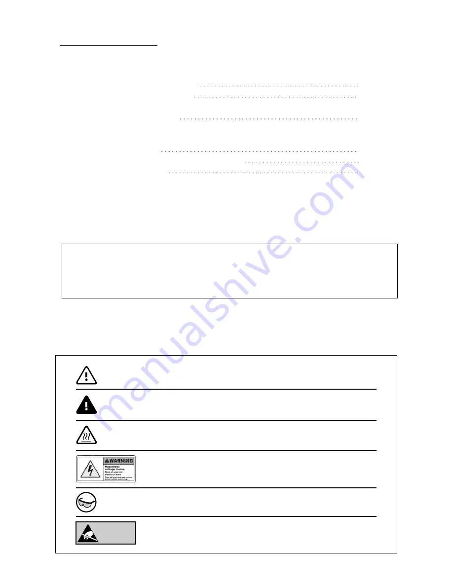
Potentially hazardous situation to be avoided.

Failure to avoid may result in minor or moderate injury.

CAUTION:

Potentially hazardous situation to be avoided.

Failure to avoid may result in serious injury.

WARNING:

Use standard electrostatic discharge precautions

ATTENTION

ELECTROSTATIC

SENSITIVE DEVICE

Beware of Hot Surface:

Some devices may radiate high temperature.

Be cautious and use safety gloves to avoid burns.

Wear safety glasses to avoid injury to your eyes.

The following safety precautions identifications are used in this manual

Turn off and lock-out system power before servicing.
Risk of electric shock or burn if failed to comply.

p3

p4~5

p6~49

2

p51~52
p53~56
p57~58

* NOTE:  THERE IS A VIDEO SERIES AVAILABLE ONLINE 
                FOR VISUAL REFERENCE FOR ASSEMBLY

Содержание PRM0282

Страница 1: ...User Guide 3D Printer 1...

Страница 2: ...d Failure to avoid may result in serious injury WARNING Use standard electrostatic discharge precautions ATTENTION ELECTROSTATIC SENSITIVE DEVICE Beware of Hot Surface Some devices may radiate high te...

Страница 3: ...lament Spool Sold separately Print platform Printer gantry 1 Rotary for 2 Press to select SD card slot Main control panel Reset button SD card insertion direction SD card not included 3 Main parts ide...

Страница 4: ...1 Box A Back Panel x1 Box E Front Panel x1 Print Platform Box B x1 Box F Left Panel x1 Top Panel x1 x1 Box D Box C Bottom Panel A C Receptacle x1 4 Filament spool holder Set DSA3302 U17 x1 SCW0188 HM4...

Страница 5: ...Nut bronze color Thin Thick Spring Bearing BER0038 x1 x1 x1 x1 x1 x4 Rod MST0600 Pre assembled Rod for Left and Right panels x2 x2 PM 3PT04 P01 x3 Timing belt Long ETP0110 Timing belt Short ETP0111 x2...

Страница 6: ...Assemble the 3D printer 2 This section will guide you through the process of building the 3D printer step by step Pre assembled pieces can be located from Boxes A to G 6...

Страница 7: ...0625 up from the bottom Anti backlash nut Small amount of brass bushing is still visible Once done there will be a slight drag while turning the lead screw A small amount of brass bushing MST0866 shou...

Страница 8: ...now be installed to the print platform by using a 2 0mm hex driver The screws go in from the top 2 1 1 TB3x12 DSA3302 U02 Back panel from Box E 2 0mm hex driver TB3x12 x2 Rod MST0600 x2 Rod MST0600 2...

Страница 9: ...so that we have approximately 2 inches exposed from the top This will help to align with the bearing 2 1 2 The movement of the bearings and rods will feel tight at this point but we will tram align t...

Страница 10: ...rt and slide it onto the bottom of the Z axis lead screw bearing facing upward BER0038 MST0651 Install the 3 screws from the back side to secure the bearing support When tightening the support screws...

Страница 11: ...prox 3mm gap for now Torque coupling MDT0142 TB3x12 SCW0153 x8 x2 Box G Next we are going to assemble the back panel to the bottom panel It is recommended to turn the back panel on its side and slide...

Страница 12: ...ll 8pcs SCW0153 screws from the backside and 2pcs SCW0157 screws from the bottom side into the rods With the back panel and bottom panel attached reposition the frame vertical to the upright position...

Страница 13: ...kes to rotate the rod During this test the lower clamp to stepper motor should not be tightened so that the motor is not rotating and only the drag of the rod is felt Now to x this problem refer to di...

Страница 14: ...crews Then loosen these 4 screws on Underneath the build platform 2 2c Tighten these screws on BOTH sides of print platform 2 2d Tighten these 4 screws at the back 2 2e By loosening the hardware the m...

Страница 15: ...will move much easier and this can be veri ed by now turning the torque coupling again and feeling a reduced amount of force needed Try turning the torque coupling again after the above procedures Th...

Страница 16: ...oth sides have the forward print platform vertical rods This requires us to install the side panel by sliding them down from the top The left panel DSA3302 U06 has the A C receptacle that needs to be...

Страница 17: ...toward the front of the printer and the tapered side toward the rear matching the panel cutout 2 5mm hex driver 7mm wrench Inner side Assembled seen from outer side 2 3 3 With the power switch recept...

Страница 18: ...ile Hong Kong is 220V There is a switch on the right side of the power supply marked 110 220V see above picture Set this switch to the appropriate position for your region If you are unsure about any...

Страница 19: ...as you are installing the right panel the sensor wires do not get pinched or caught on anything Sensor wires 2 3 6 TB3x12 SCW0153 x8 x4 Right panel installation Box G Find the following accessories f...

Страница 20: ...installed carefully lay the printer on it s side Loosely install these screws without tightening them as we need to align and tram the rods later Example on the right 2 3 9 2 5mm hex driver 2 0mm hex...

Страница 21: ...ow diagram Tighten these screws all the way as they will start to be the alignment points for tramming the frame later We are done with the bottom so let s turn the printer back upright Great job so f...

Страница 22: ...x sensor wires through the loop together with the wires down from the back right corner and through another loop picture 2 4b Next route the Y min sensor wire together with all the wires from point 1...

Страница 23: ...crew see below diagram Loosen this set screw on adapter Now carefully slide the rod through the two support bearings on the X axis gantry see below diagram and picture The direction and side is not im...

Страница 24: ...tern below right Now repeat this procedure on the other support bearing block Loosen these 4 screws on each support bearing block 1 2 3 4 Cross pattern example when tightening 2 6 1 Now let s install...

Страница 25: ...supports parallel to the side panel before sliding it down Note the extruder head goes toward the front and the fan toward the rear Loosely install MDT0140 2pcs with 12mm wrench at the back 2 0mm hex...

Страница 26: ...orth and left and right if necessary an adjustment to the inner gantry rods can be made to adjust the X axis length by losing the 3 rod set screws shown in below pictures and sliding the gantry to the...

Страница 27: ...front of the printer to give an unobstructed access to the belt area picture 2 7a We need to route the belt around the motor sprocket with the long side toward the back and the short end toward the f...

Страница 28: ...ure 2 7c and 2 7d 2 0mm hex driver Picture 2 7d Slide the lock down and reinstall the screws Run the other end of the belt threw the guide block and around the pulley on the left side picture 2 7e Rem...

Страница 29: ...otor and pulley and in the guide block picture 2 7i Picture 2 7h Picture 2 7i We need to adjust the tension on the belt now Slide the extrusion head to the far right Now slowly turn the tensioning scr...

Страница 30: ...that magnets on extruder heater thick red wires temperature sensor thin black wires coming from the extruder cover by the thick red wires extruder wires multi colored 4 wires and the rear fan thin red...

Страница 31: ...o the front left position and lay the wire in the back panel slot making an L shape picture 2 8f and 2 8g This L shape will give the required slack for the print head to move around and the wires not...

Страница 32: ...un the wires toward the front and down zip tying it to the left panel where noted in the picture picture 2 8k Picture 2 8j Picture 2 8k Let s switch to the right side we need to gather the side motor...

Страница 33: ...hrough the most bottom right back cutout and bring them down and towards the front pictures 2 8n and 2 8o Picture 2 8n Picture 2 8o Now tighten the zip ties and tidy the wires up making sure none of t...

Страница 34: ...e and slide in the front panel with the plastic parts facing toward the inside picture 2 9a Note make sure not to pinch any wire in the front panel Front Panel 2 8 1 Picture 2 9a These plastic parts f...

Страница 35: ...Find the following accessories from MDT0140 x2 Nut silver color TB3x12 x8 x4 Install all screws loosely rst Once all are installed tighten them up and install the 2 nuts on the Y axis rods picture 2 9...

Страница 36: ...set screws on the ex collars to free the shaft from each other Do not remove the screws Just loosen them so the collar can rotate independently from the motor shaft pictures 2 9c and 2 9d Picture 2 9c...

Страница 37: ...rew so the belt tension block is toward the back picture 2 9e Now remove the front belt lock and install the belt like we did before picture 2 9f Picture 2 9e 2 9j Now wrap the belt through the front...

Страница 38: ...to rear a few times and re check the tension Remove the tensioning belt block and lightly pulling on the belt mesh the teeth with the block and reinstall the block onto the tensioning screw picture 2...

Страница 39: ...ts to match the looser of the two belt tension Once done slide the gantry to approximately the center having the two set screws on the ex collars we loosened before facing up so we can get to them eas...

Страница 40: ...e SCW0143 TB4x14 16pcs Box G Find the following accessories from x16 Fit the top panel in place and make sure it seats at and the small hole is to the right Now install 16pcs of SCW0143 screws to hold...

Страница 41: ...cture 2 10c Picture 2 10d We will now install the lament spool support The two upright supports are bolted to the side panels with 4 SCW0188 screws picture 2 10e The two supports have an inside and an...

Страница 42: ...2 10 3 The Spool drum slips on to the axle and sets into the two upright supports we just installed picture 2 10i Picture 2 10g Picture 2 10h Picture 2 10i Filament roll Sold separately 42...

Страница 43: ...cture 2 11a Picture 2 11b Picture 2 11c Start with the position sensor wires pay attention to the color vs pin position There is a total of 6 position sensors 2 for each axis picture 2 11b It may help...

Страница 44: ...ning the screw clockwise it closes the terminal securing the wire picture 2 11f We are starting at block D10 which is the extruder heater The two thick red wires need to have the insulation carefully...

Страница 45: ...s together red to red and black to black picture 2 11i Install the black wire set in it s denoted spot rst These wires are a bit smaller so once you start to feel the wires compress tighten one full t...

Страница 46: ...wires are small picture 2 11m Picture 2 11l Board cooling fan wires Loosen the top red and black terminal wires and slip the front board fan wires in matching red and black Then re tighten the termina...

Страница 47: ...l panel to the printer and tidy up the wiring Install the 4pcs SCW0143 screws in the front panel leaving them slightly loose picture 2 11q 2 5mm hex driver Box G Find the following accessories from TM...

Страница 48: ...up picture 2 11r Picture 2 11r Now install 4pcs SCW0039 screws from the inside picture 2 11s and below diagrams 2pcs on the left 2pcs on the right Once done tighten the 4 outer screws we previously in...

Страница 49: ...2 11 3 Congratulations your 3D printer is now assembled We still need to level the print bed and check the functionality This will be covered in the setup guide 49...

Страница 50: ...50 Operational checks and preprint setup 3 This section will guide you through the process of operations checks and preprint setup...

Страница 51: ...mbly Attach the A C power cable to the left side port with the power switch in the off position picture 3 1c Make sure the power plug matches to the type of receptacle appropriate to your region as we...

Страница 52: ...e LED light goes out this is why we moved the extruder to the middle If you don t have a red light on one of the sensors turn the power off and make sure the print head or print platform is away from...

Страница 53: ...check 1 Rotary for or navigate 2 Press enter to con rm selection Reset button Once we give the command to auto home the print head will rst move to the left then to the front followed by the print bed...

Страница 54: ...nter power off There are 4 bolts around the print bed that adjust its height Using a straight edge such as a ruler adjust the bed using a 7mm wrench to lower the printing plate level to the clear side...

Страница 55: ...ight turn off the printer and remove the two business cards We will now set the level and ne tune the setting With the power off slide one business card between nozzle and the bed using a 7mm wrench l...

Страница 56: ...at PLA Commented temperature Commented temperature Once you select the preheat you will hear the fans come on and the temperatures on the main screen will indicate a requested temperature on the right...

Страница 57: ...Lift off the spool axle and drum unthread the drum end cap and slide your lament spool onto the drum and replace the axle picture 3 3a Install the Axle and spool so the lament unwinds to the front of...

Страница 58: ...st the roller use tweezers to help guide the lament into the center of the white seal picture 3 3d and continue to push the lament down till you see some come out of the print head Congratulations You...

Страница 59: ...online under the les tab of the 3D printer on www HobbyKing com There is also an active forum on http www rchouse com dedicated to the HobbyKing 3D printer Assemble tips and tricks trouble shooting v...

Страница 60: ...PRM0282...

Отзывы: