12
corresponding ones of J1-J6 are X/Y/Z/RX/RY/RZ.
Note: When the fifth joint is in the zero position, the robot is at a singular point. In
this case, rectangular coordinates cannot be used for teaching. You should first switch to
the
【
joint
】
coordinate system and move the five axes out of the zero position.
2.2.3 Tool coordinate system
1) Definition of tool coordinate system
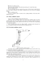
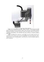
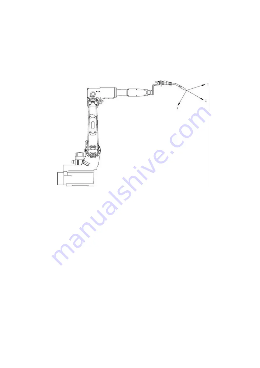
Figure 2-5 Tool coordinate system diagram
The coordinate system is defined on the tool and is defined by the user. Generally, the
effective direction of the tool is defined as the Z axis direction of the tool coordinate
system, and the X axis and Y axis directions are defined by the right-hand rule.
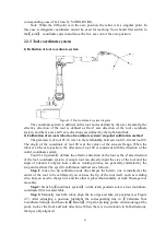
2) Calibration of six-axis robot tool coordinate system: six-point calibration method
The parameters of tool 01-10 refer to the relationship between tool 01-10 and tool 00.
The origin of the coordinate of tool 00 is at the center of the six-axis flange. When the
robot is at the zero position, the direction of tool 00 is consistent with the direction of the
world coordinate system.
Tool 01-10 generally defines the effective direction of the tool as the Z axis direction
of the tool coordinate system. A simple tool can directly input the size of the tool and the
angle of rotation. Complex tools, such as welding torches, are generally calibrated by the
six-point method. The specific calibration method is as follows:
Step 1:
make two tip calibration rods (the sharper the better), one is installed at the
center of the tool to be calibrated (you can use the tip of the tool itself, such as welding
wire, but you need to sharpen it), and the other is placed horizontally at work On stage (not
movable).
Step 2:
Switch to
【
coordinate system
】
on the teach pendant, select a tool coordinate,
coordinate 00 is not selectable.
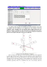
Step 3:
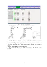
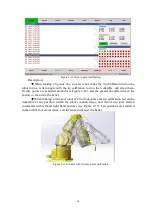
Manually teach the robot, align the two tips and take six postures (see Figure
2-7). After adjusting a position, highlight the corresponding line in
【
Calculate Tool
Coordinate Value
】
, and then click
【
Record
】
. (Tips for picking points: when looking at the
point, look at the front and side directions. When there is no deviation in both directions,
the tip is only aligned.)
Содержание TKB80306
Страница 1: ...Shanghai Turing Intelligent Manufacturing Robot Co LTD ...
Страница 6: ...IV IV 8 2 Common faults and treatment 82 ...
Страница 52: ...46 Figure 3 49 Sorting files ...
Страница 56: ...50 Figure 4 4 System V variables Figure 4 5 System S variables ...
Страница 79: ...73 Figure 6 8 Log print settings ...


